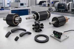



Position and angle sensors do not work from electronics alone. In magnetic sensing systems, the sensor IC reads the field created by a magnet target, then converts that field into speed, position, or angle data. If the magnet is not matched to the air gap, sensing direction, pole pattern, and working environment, the final signal can drift even when the IC and circuit are well selected.
For position sensors, the more useful question is: what kind of magnetic target does this application need?
Why Standard Magnets Often Fall Short
Many position sensor projects begin with a simple magnet drawing or a requested gauss value. That is rarely enough. A magnetic target for a position sensor must provide the right field at the sensor IC, not just a strong field at the magnet surface.
A standard magnet may fail for several reasons:
- The air gap changes after the magnet is mounted into a housing, shaft, or rotor.
- The field is strong at the surface but too weak or uneven at the sensor position.
- The part shape does not fit the compact sensor package.
- The pole pattern cannot support the required output signal.
- The material cannot handle heat, moisture, impact, or automotive vibration.
- Manual assembly introduces eccentricity, tilt, or pole misalignment.
For these reasons, position sensor magnets are usually better designed as custom magnetic components or integrated magnetic assemblies, especially in high-volume automotive and robotics applications.
Three Design Steps for Custom Sensor Magnets
The design process can be simplified into three linked decisions: material, geometry, and magnetization.
1. Choose the right magnetic material
Material selection affects flux output, temperature stability, corrosion resistance, mechanical strength, and cost. Ferrite-based compounds are often used when cost, corrosion resistance, and dimensional stability matter. NdFeB-based compounds can provide stronger output in compact space. SmFeN can be considered when rare-earth performance and environmental stability are both important.
For many sensor projects, injection molded magnets are attractive because magnetic powder and polymer binder can be processed into complex shapes. They can also be molded around inserts, hubs, shafts, or carriers to reduce later assembly steps.
2. Use injection molding to integrate the sensor magnet
For position sensors, magnet shape is not only a mechanical detail. The geometry affects air gap, field distribution, mounting stability, and the final signal read by the sensor IC.
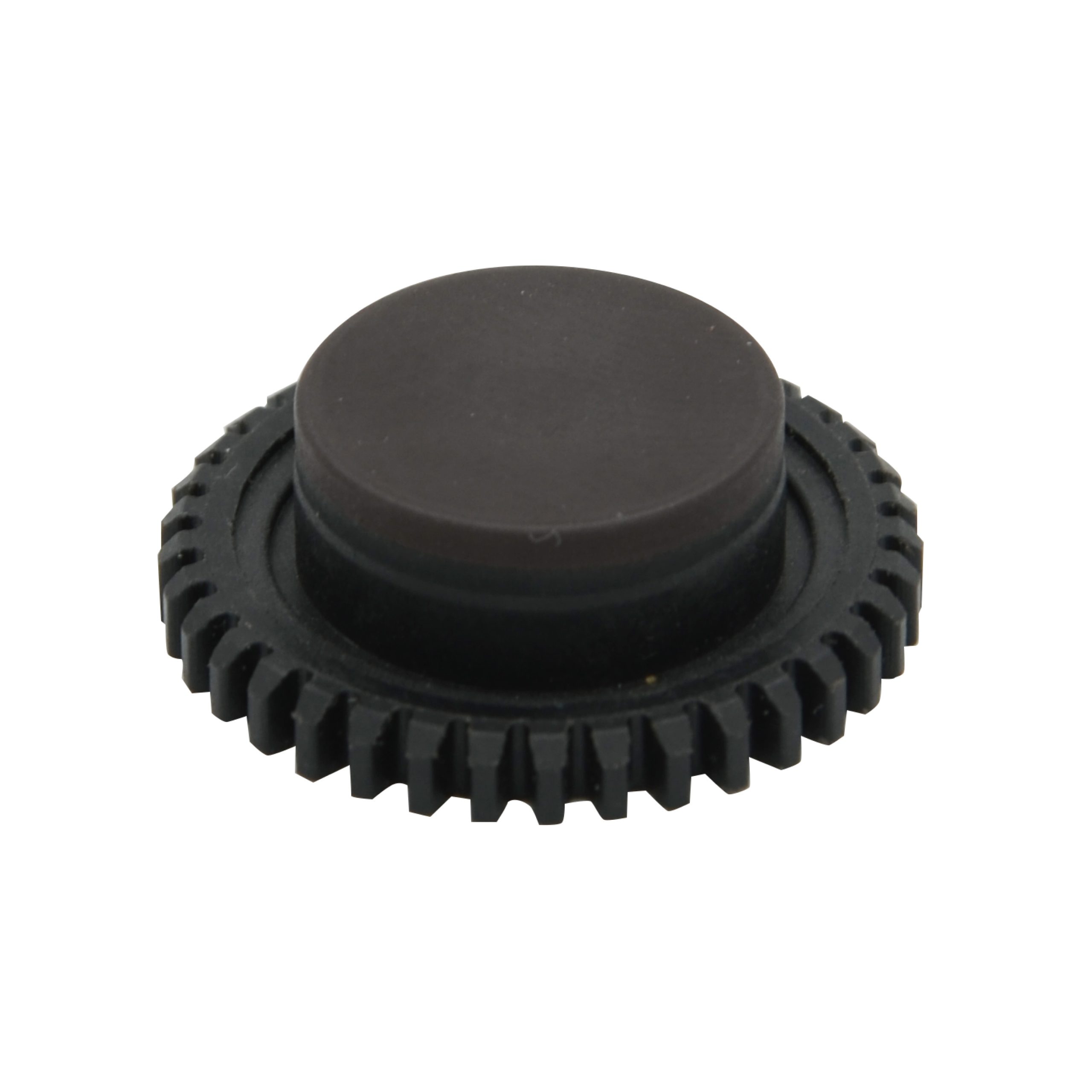
This is where injection molding becomes useful. Instead of forcing a simple block or ring magnet into a compact sensor package, the magnetic component can be molded around the available space. Holes, thin walls, sleeves, hubs, ribs, gears, and mounting features can be built into the part so the magnet fits the sensor module more accurately.
Injection molding can also support insert molding around shafts, carriers, or metal sleeves. This helps reduce looseness, bonding error, eccentricity, and assembly variation, which are common causes of unstable position sensor signals.
3. Define the magnetization pattern
After molding, the magnet still needs the correct pole pattern. Depending on the sensor, the part may require diametric magnetization, axial magnetization, radial magnetization, multi-pole magnetization, or a custom pattern with reference features.
The magnetizing fixture is therefore part of the sensor design, not an afterthought. It must create the required pole location, direction, and field balance repeatedly in production.
Application 1: Automotive ABS Sensor Rings
In an ABS system, the wheel-speed sensor reads a magnetic ring or tone target to detect wheel rotation. The sensor must work near the wheel hub, where it may face vibration, impact, water, mud, road salt, and temperature cycling.
This is very different from a clean laboratory angle sensor. The magnetic ring must provide a stable signal while also surviving the mechanical environment. Rubber magnets may be used in some low-demand designs, but exposed wheel-end applications often require better dimensional stability, toughness, and magnetic output.
An automotive ABS sensing ring can use bonded magnetic material with insert molding, allowing the magnetic ring and metal carrier to become a stronger integrated part. This helps the ring mount directly on the wheel hub while maintaining magnetic output and mechanical resistance.
For ABS magnets, key design checks include pole count, ring concentricity, surface field, air gap to the probe, impact resistance, and field consistency around the full circumference.

Application 2: EPS Steering Position and Angle Sensing
Electric power steering systems need reliable angle, position, or torque-related feedback. Depending on the system architecture, magnetic sensing may be used around the steering shaft, motor, gear structure, or actuator module.
EPS sensors have several design pressures at once: compact space, high reliability, temperature variation, vibration, and strict signal repeatability. The magnetic target must be small enough to fit the steering assembly but stable enough to support accurate position feedback.
For this kind of angular measurement, angle sensor magnets can use multi-pole magnetization and injection molded structures to match the sensor location. The design should define the sensor air gap, field range at the IC, allowed eccentricity, temperature range, and whether the output is absolute angle, limited-angle position, or speed-related feedback.
In EPS applications, the best magnet is not simply the strongest one. It is the magnet that keeps the field inside the sensor’s usable window across assembly tolerance and service life.
Application 3: Robot Joint Position Feedback
Robot joints need compact, repeatable position feedback in a moving structure. The sensor may be placed near a hollow shaft, harmonic drive, motor rotor, or joint housing. Space is limited, and the joint may experience shock, vibration, cable routing constraints, and repeated acceleration.
Robot joint sensor magnets are usually designed for compact geometry and stable magnetic signal output. Compared with a standard loose magnet, a custom molded magnetic ring or thin magnetic target can better match the joint structure and reduce assembly error.
For robot joints, engineers should confirm the sensing direction, magnet thickness, air gap range, allowed runout, output requirement, and whether a single-track or multi-track magnetic pattern is needed. If the joint needs high repeatability, pole balance and waveform quality become as important as nominal magnetic strength.
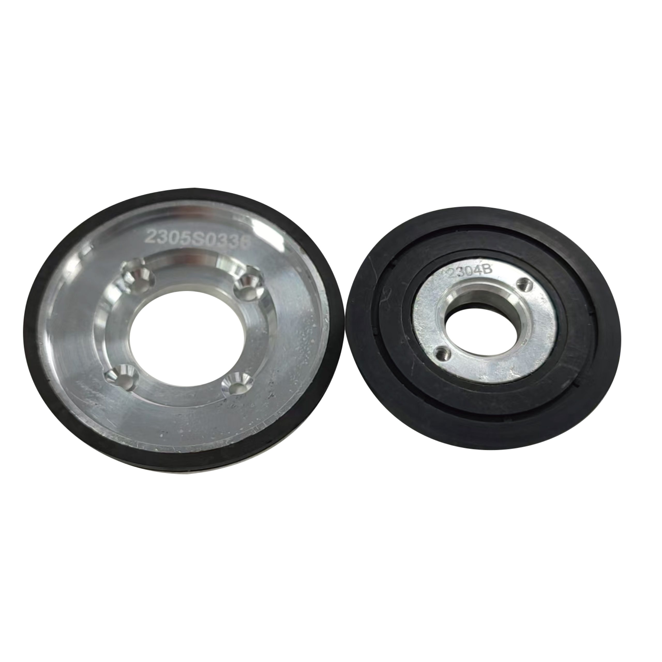
What Engineers Should Specify
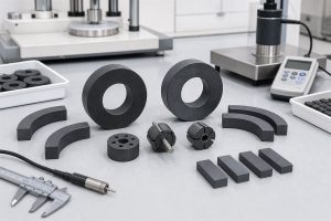
Before ordering a custom position sensor magnet, the specification should include more than material grade and surface gauss. A practical checklist includes:
- Application type: ABS, EPS, robot joint, gear position, motor feedback, or another sensor module
- Sensor IC location, sensing axis, and nominal air gap
- Magnet geometry, mounting method, and reference surfaces
- Required field range at the sensor position
- Magnetization direction, pole count, pole pitch, and reference feature
- Operating temperature, humidity, vibration, impact, and chemical exposure
- Tolerance stack-up, runout, and eccentricity limits
- Inspection method, including field map, waveform test, and assembled-signal validation
Early magnetic simulation can help predict whether the field reaches the IC correctly, while production quality control should verify that the molded and magnetized parts remain consistent.
Conclusion
Position and angle sensor magnets should be designed from the application outward. ABS sensor rings, EPS steering sensors, and robot joint sensors all need stable magnetic fields, but their mechanical environments and signal requirements are different.
The right custom magnet is defined by material, shape, magnetization, air gap, and validation method together. For high-volume sensor assemblies, injection molded magnetic components can reduce part count, improve repeatability, and make the magnetic target easier to integrate into the final product.
Chase Technology supports custom magnetic components for automotive and robotic position sensing, including ABS sensing rings, angle sensor magnets, robot joint sensor magnets, and other application-specific magnetic assemblies.
FAQ
What magnet is used in an ABS sensor?
ABS sensors often use a magnetic sensing ring mounted near the wheel hub. The ring needs stable pole spacing, good concentricity, impact resistance, and consistent field output around the full circumference.
Why are injection molded magnets useful for EPS sensors?
Injection molded magnets can combine magnetic material with complex shapes, inserts, hubs, or carriers. This helps EPS position sensors fit compact steering assemblies while keeping the magnetic target repeatable in mass production.
What matters most in a robot joint sensor magnet?
Robot joint sensor magnets need compact geometry, controlled air gap, low runout sensitivity, and stable waveform quality. For high repeatability, pole balance can be as important as magnetic strength.
Is stronger magnetic flux always better for position sensors?
No. The magnet should keep the field inside the sensor IC’s usable range. Too little flux can create noise, while too much flux can saturate the sensor or increase angle error.