

Choosing a magnet for a rotary sensor looks easy at first. Pick a small neodymium disc, place it above the chip, and rotate it. Then the first prototype arrives, and the angle jumps near 180 degrees. Or the signal works on the bench but drifts when the air gap grows.
You have probably seen this before. And it is rarely the magnet’s fault on its own. The problem starts earlier, when the magnet is treated as a separate component instead of part of one magnetic system. The sensor IC, the shaft, the housing, and the air gap all shape the field the chip actually sees.
So the right magnet is not always the strongest one. It is the one that keeps the field direction and amplitude inside the IC’s window across the full rotation, the full temperature range, and the full tolerance stack. That is what makes the output predictable in the finished assembly.
How Does a Magnetic Rotary Sensor Use a Magnet?
A magnetic rotary sensor measures a changing magnetic field as a shaft turns. The magnet rotates with the shaft. The sensor IC stays fixed on a PCB or housing. Hall, AMR, GMR, or TMR elements measure selected field components, and the electronics convert those signals into an angle.
That description sounds universal, but sensor architectures differ. Some ICs calculate angle from in-plane Bx and By components. Others measure a differential Bz pattern. A magnet that works well with one architecture may give a weak or distorted signal with another.
This is why I would always start with the sensor datasheet or application note. The measurement principle, magnet geometry, gap, displacement, and temperature work together. Your chosen IC should define the design window. If you are building a compact shaft-position system, Chase’s angle sensor magnet solutions show the type of integrated magnetic target this process produces.
Start With the Magnetic Rotary Sensor Requirements
Before looking at magnet grades, write down what the sensor needs to see. Check the minimum and maximum field, the measured axes, the usable field angle, and any saturation limit. Also confirm whether the IC expects a two-pole target, a multipole ring, or another field pattern.
- Required field components at the sensing element
- Minimum and maximum flux density
- Allowed angle error and output noise
- Nominal and worst-case air gap
- Maximum shaft offset, tilt, and runout
- Operating and storage temperature
- Rotation speed and required response time
- Nearby steel, motors, currents, or external magnetic fields
Use the actual sensing-element location, not just the top of the plastic IC package. Package thickness can add meaningful distance in a compact design.
Choose the Correct Magnetization Direction
For many 0-to-360-degree shaft-end sensors, the starting point is a diametrically magnetized two-pole disc, cylinder, or ring. North and south sit on opposite sides. As the magnet turns, the field direction rotates once per mechanical revolution.
AMR angle sensors often need this in-plane rotating field. In that arrangement, a diametric rather than axial magnetization provides the changing field direction used to calculate angle.
Still, do not copy that choice blindly. Some Hall ICs use a different field component or differential layout. Match the pole orientation to the selected chip. If you need a through-shaft design, a diametric ring may preserve the center bore.
Select the Magnet Shape and Size
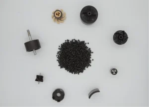
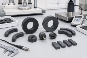
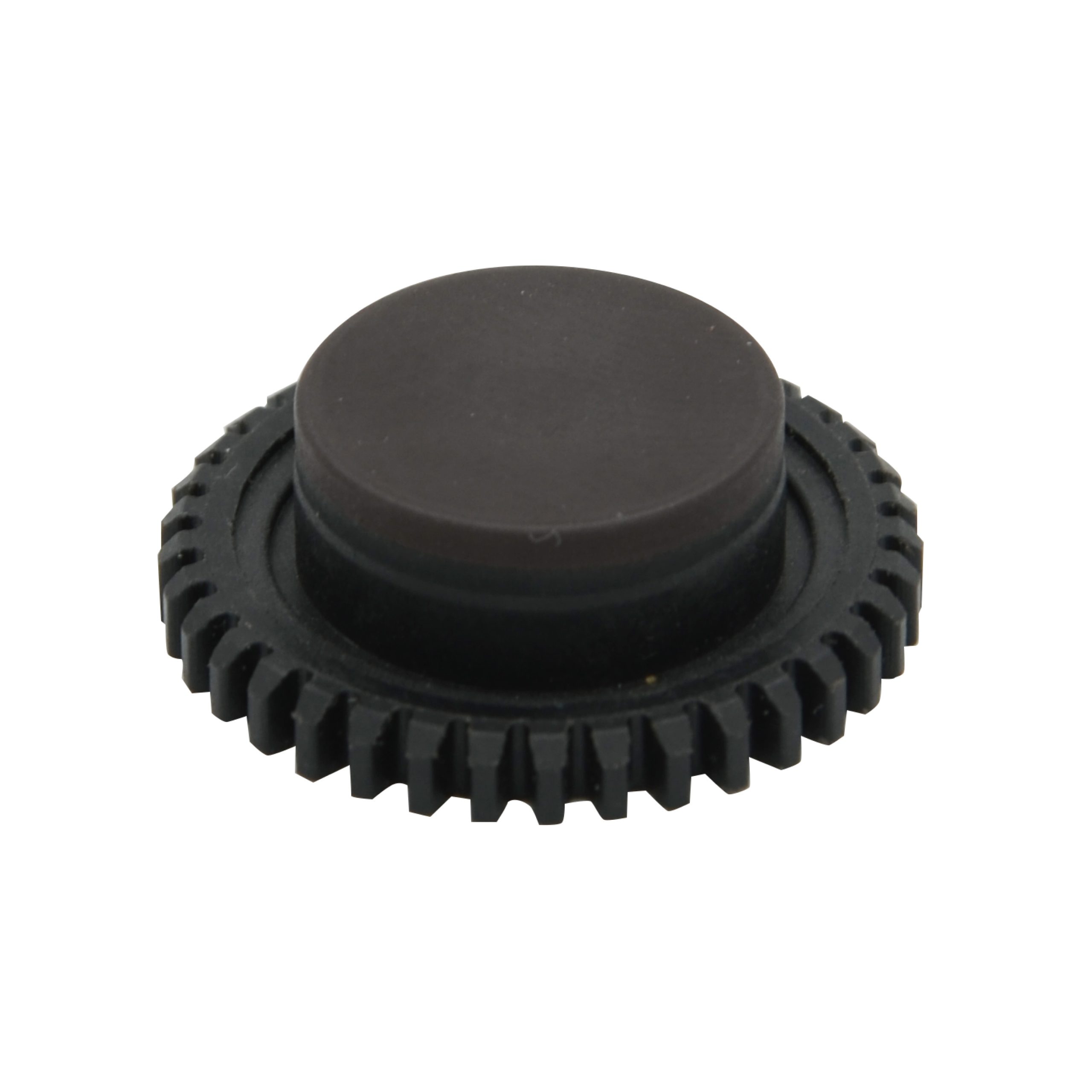
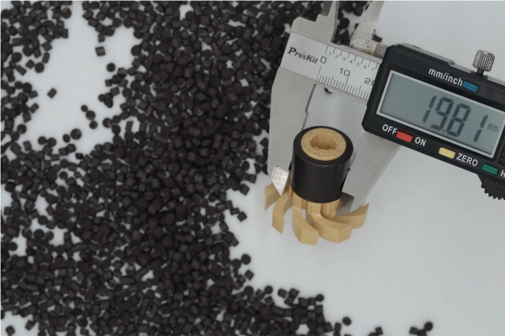
A disc or cylinder is common for an end-of-shaft layout. A ring works when the shaft must pass through the center. A molded target can add a hub, key, sleeve, or insert when the magnetic part also needs a mechanical interface.
Diameter and thickness do different jobs. More thickness can increase the available field, but only up to the point where extra material adds little value. A larger diameter may improve tolerance to lateral offset, yet it can also change the field amplitude and packaging space. The best ratio depends on the IC and the working gap.
Do not simply make the magnet as large and strong as possible. A large magnet can still have field-homogeneity issues, while excessive field may force a larger gap to avoid saturation. A compact, balanced design is usually better than brute force.
Match the Magnet Material to the Environment
| Magnet material | Why you might choose it | What to check |
|---|---|---|
| Sintered NdFeB | High field from a small volume | Corrosion protection, brittleness, temperature, and assembly stress |
| SmCo | Good temperature stability and corrosion resistance | Higher cost and mechanical brittleness |
| Injection-molded NdFeB | Precise shapes, molded features, and repeatable production | Lower field than sintered NdFeB of similar size |
| Compression-molded magnets | Accurate rings with higher magnetic loading than many injection-molded options | Geometry, tooling, and assembly requirements |
| Bonded ferrite | Cost control, corrosion resistance, and molded integration | Larger volume may be needed to meet the field window |
If your package is very small, sintered magnets may be the natural first option. If you need an integrated hub or high-volume molded target, injection-molded magnets may reduce assembly steps. Precision rings may also suit Chase’s compression-molded magnet process. For higher temperatures, compare coercivity and reversible temperature behavior rather than relying on a simple maximum-temperature label.
Design the Air Gap and Misalignment Together
Air gap is not one fixed number. It includes the nominal space, sensor package depth, PCB position, adhesive thickness, shaft movement, bearing clearance, housing tolerance, and thermal expansion. Calculate the minimum and maximum effective gap.
Then add lateral offset, tilt, and runout. These errors can make two signal channels unequal and create angle nonlinearity even when the total field looks strong. A larger magnet diameter can sometimes improve offset tolerance, but simulation should confirm it. Chase can evaluate these cases through its magnetic simulation service before you freeze the shaft-end layout.
Check Mounting, Temperature, and Magnetic Interference
A correct magnet can still fail in a poor assembly. Define how you will control its center, height, angular pole index, and axial retention. Review adhesive cure temperature, press-fit stress, overmolding pressure, and balance at speed. A chipped coating or tilted magnet can change both durability and accuracy.
Also model the nearby hardware. Steel shafts and housings can redirect flux. Motor magnets, current-carrying cables, and external fields can bias the sensor. If these parts are present in the final product, include them in simulation and testing.
Validate the Complete Magnetic Rotary Sensor Assembly
I would validate minimum, nominal, and maximum tolerance cases before tooling. Start with magnetic simulation, then build production-intent samples. Use the planned magnet grade, coating, magnetization fixture, shaft, adhesive, PCB, and housing.
- Record raw field channels and calculated angle through 360 degrees.
- Test minimum and maximum air gaps.
- Add planned eccentricity, tilt, and shaft runout.
- Repeat at low and high operating temperatures.
- Check startup position, rotation speed, and output noise.
- Test after vibration, thermal cycling, humidity, and assembly stress.
- Inspect magnetization angle, magnetic moment, dimensions, and mechanical datum.
The goal is not to prove that the magnet is strong. The goal is to prove that the sensor stays accurate across production variation. Chase Technology can connect the design targets to repeatable checks through its production quality-control capability.
Magnetic Rotary Sensor Magnet Selection Checklist
- Sensor IC and measured magnetic axes
- Required field range and saturation limit
- Two-pole or multipole field pattern
- Magnet shape, diameter, thickness, and bore
- Magnetization direction and angular index
- Material, grade, coating, and temperature range
- Nominal and worst-case air gap
- Offset, tilt, runout, and balance limits
- Mounting and retention method
- End-of-line magnetic and sensor-output test
If you send this information to the suppliers, you will get a much more useful answer than asking for “a strong magnet for a rotary sensor.” For broader encoder architecture and pole-count decisions, see our magnetic encoder magnet guide.
FAQs
What Magnetization Is Best for a Magnetic Rotary Sensor?
A diametrically magnetized two-pole disc, cylinder, or ring is common for 360-degree angle sensing. However, the correct pole pattern depends on the field components measured by your specific sensor IC.
Is a Stronger Magnet Always Better?
No. Too little field can reduce signal quality, while too much field can saturate the sensor or require an impractical gap. Choose a magnet that stays inside the IC’s usable field window at every tolerance and temperature condition.
Can I Use a Ring Magnet Instead of a Disc?
Yes, if the ring produces the required field and magnetization pattern at the sensor. A ring is useful for through-shaft packaging, but its bore changes the magnetic circuit, so validate it rather than assuming it behaves like a solid disc.
What Information Should I Send for a Custom Magnet Review?
Send the sensor datasheet, mechanical drawing, air-gap range, shaft tolerances, temperature, speed, target angle error, material restrictions, annual volume, and available assembly space. You can share the project through our magnet engineering contact page.