

When engineers choose a rotary position feedback solution, it is easy to start with a number: 12-bit, 17-bit, 23-bit, or a target pulse count. But resolution only describes how finely a signal can be divided. It does not decide whether the encoder can survive the real machine environment.
For encoder selection, the better order is:
working conditions > sensing principle > resolution specification.
If the equipment runs in a clean laboratory, precision machine tool, or optical inspection platform, an optical encoder may be the right first choice. But if the encoder must work around dust, oil, moisture, cutting fluid, vibration, shock, shaft runout, compact space, or temperature changes, a magnetic encoder often deserves to be evaluated first.
The reason is straightforward. A magnetic encoder does not rely on a clean optical path. It reads changes in a magnetic field between a magnetic target and a sensor IC, then converts those changes into position, speed, angle, or commutation feedback. This makes the structure easier to seal, more tolerant of contamination, and better suited to compact rotary assemblies.
Start with the Working Conditions
A magnetic encoder is especially worth considering when the application includes dust, oil mist, water vapor, textile fiber, metal particles, cutting fluid, continuous vibration, shock, compact installation space, or a need for non-contact sensing. It is also useful when the magnetic target, carrier, and mounting structure can be integrated for high-volume production.
This does not mean magnetic encoders are better in every case. Optical encoders still have strong advantages in very high precision and clean environments. But in industrial equipment, electric vehicles, conveyors, pumps, valves, robotic joints, textile machines, and automation systems, the real challenge is often contamination, vibration, space, tolerance, cost, and uptime.
Encoder Technologies: A Practical First Filter
| Encoder type | Main advantages | Main limitations | Common fit |
| Optical encoder | High accuracy and high resolution | Sensitive to dust, oil, moisture, vibration, and optical alignment | Clean precision equipment |
| Magnetic encoder | Tolerant of contamination, shock, and vibration; compact; non-contact; cost-effective | Must control air gap, runout, magnetic interference, and magnetization quality | Industrial equipment, motors, conveyors, EVs, pumps, valves, robotic joints |
| Inductive encoder | Robust, no optical path | Higher system complexity and cost | Servo systems and harsh industrial motion control |
| Capacitive encoder | Compact and low cost | Sensitive to moisture, contaminants, and structure variation | Consumer electronics and small knobs |
| Resolver | Very robust, high temperature capable | Higher cost, larger size, complex decoding | Aerospace, mining, metallurgy, heavy-duty drives |
The key point is not that one technology is always superior. The key point is to match the measuring principle to the working environment. Choosing only by bit count can hide the real failure mode. A high-resolution optical encoder may perform well on a test bench but lose reliability if oil mist, dust, condensation, or vibration compromises the optical path.
What a Magnetic Encoder Measures
A typical magnetic encoder includes two core elements:
- A magnetic target, such as a diametric magnet, single-pole-pair magnet, pole wheel, or multi-pole magnetic ring
- A magnetic sensor IC, such as a Hall-effect, AMR, GMR, or TMR sensor
The magnet is mounted to the shaft, rotor, wheel, gear, roller, or rotating bracket. The sensor is fixed on the PCB or housing. As the part rotates, the sensor detects changes in magnetic field direction or strength. The electronics then output absolute angle, incremental A/B/Z pulses, UVW commutation, analog sine/cosine, or digital signals such as SPI, SSI, and PWM.
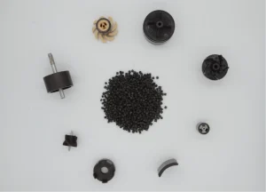
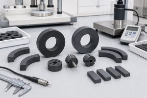
For example, this magnetic design can be used in angle sensor magnets, robot joint sensor magnets, and other application-specific magnetic assemblies.
So the first technical question is not only “What is the accuracy?” It is also: Does the controller need absolute position, incremental feedback, speed measurement, commutation, or several outputs at once?
Single-Pole Magnet or Multi-Pole Magnetic Encoder Ring?
After the working conditions and feedback requirements are clear, the next question is the magnetic target structure.
Single-pole-pair magnet
A single-pole-pair or diametrically magnetized magnet is commonly used for 360-degree absolute angle sensing. It is simple, compact, and suitable for shaft-end sensing in small motors, knobs, actuators, valves, and compact joint modules.
This is often the better starting point when the system needs absolute shaft position immediately after power-on.
Multi-pole magnetic ring
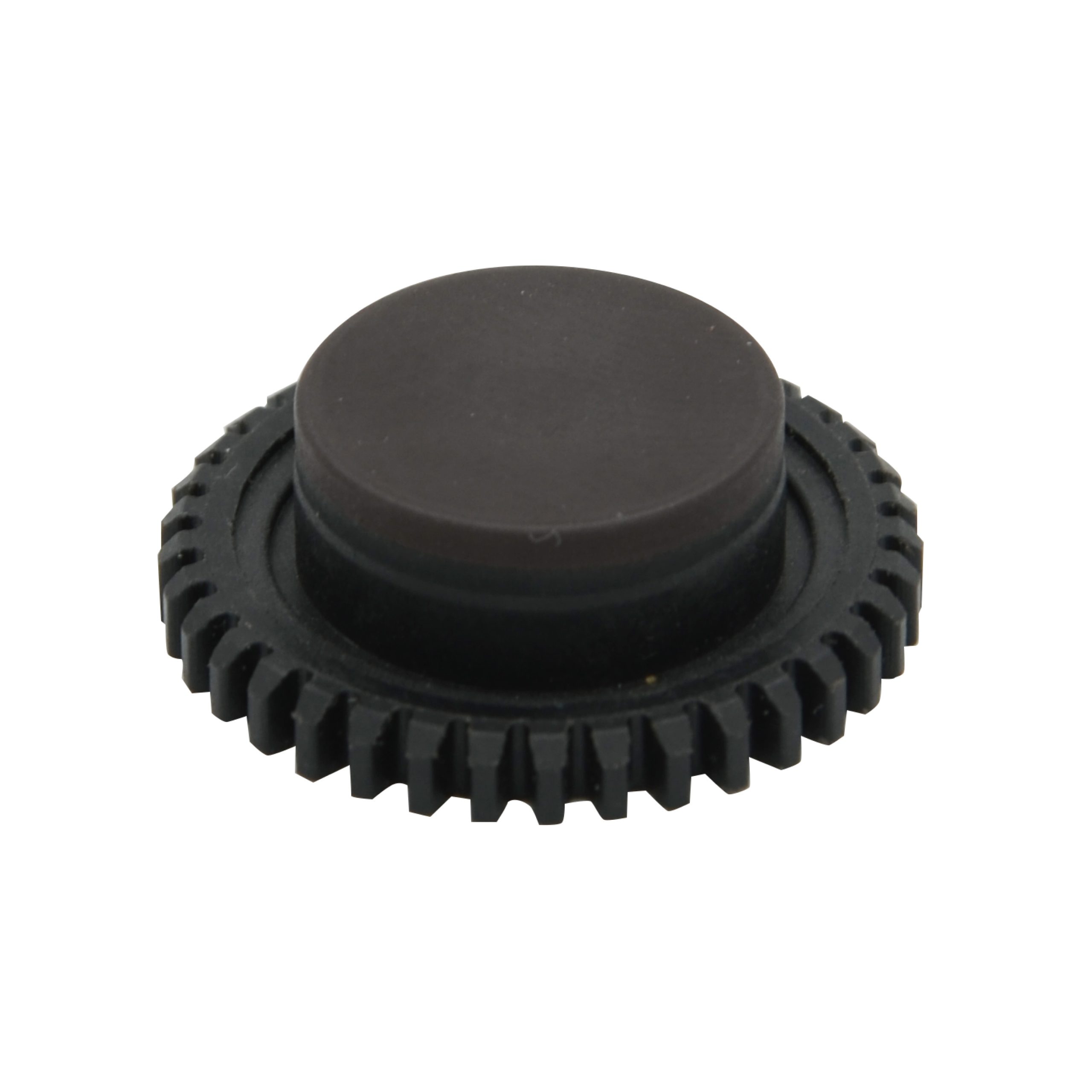
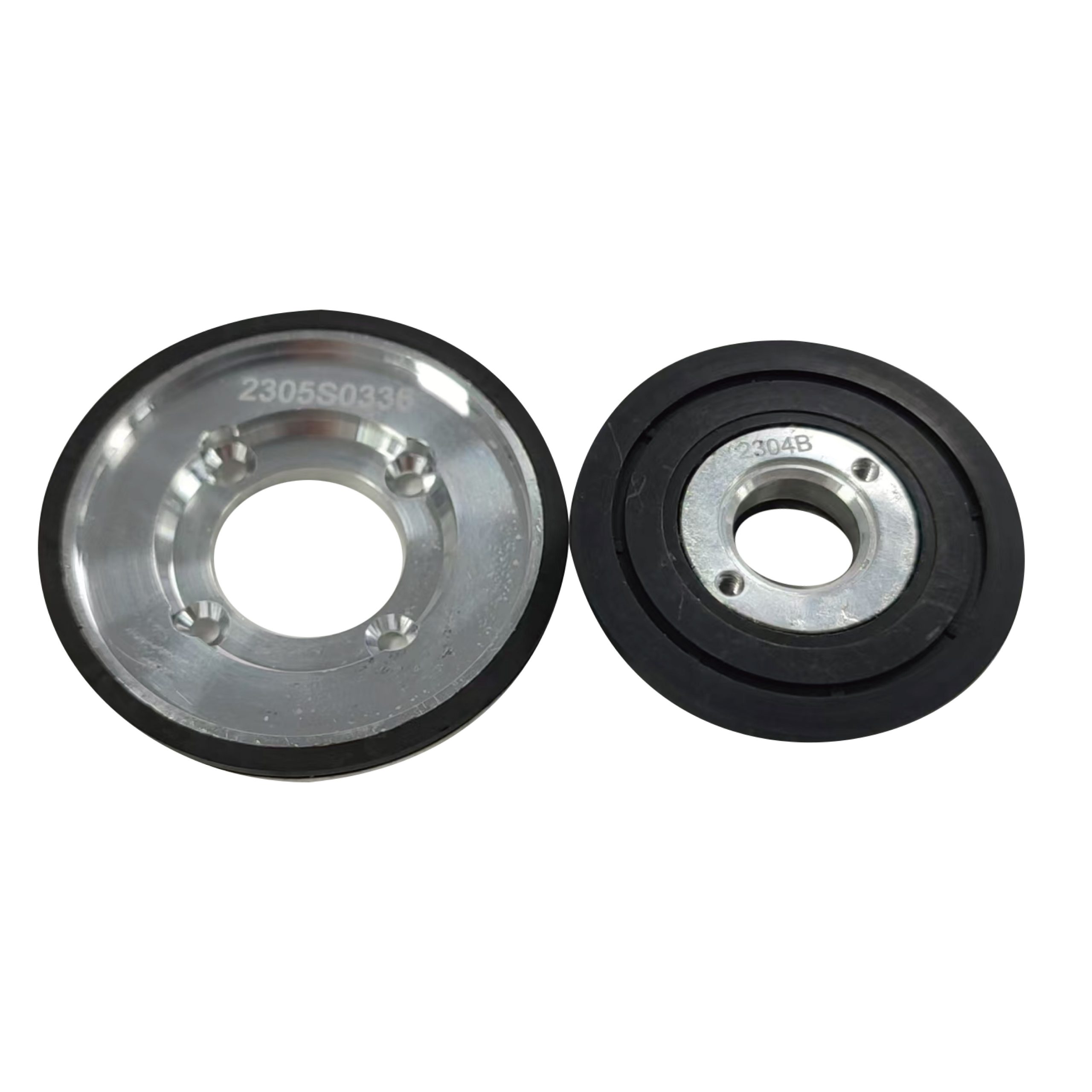
A multi-pole magnetic encoder ring has alternating north and south poles around a circular track. As the ring rotates, the sensor reads multiple magnetic cycles per revolution. This makes multi-pole rings useful for speed feedback, incremental position feedback, higher pulse counts, and compact motor or roller applications.
Multi-pole rings are common in motor feedback systems, conveyor rollers, robot joints, wheel hubs, electric tools, compact pumps, and flow rotors.
But more poles are not automatically better. As pole count increases, pole pitch becomes smaller:
Pole pitch = sensing-track circumference / number of individual poles
If the pole pitch is too small for the sensor distance, magnetizing process, or mechanical tolerance, the waveform can become weak, distorted, or unbalanced. A high pole count that looks attractive on paper may produce a poor signal in the real assembly.
Single-track, radial, and dual-track rings
Multi-pole rings can also differ by reading direction and track design.
- Axial rings are read from the top or bottom face.
- Radial rings are read from the outer or inner diameter.
- Single-track rings use one magnetic pole track.
- Dual-track rings use two tracks, sometimes with different pole counts, to support reference information, redundancy, or absolute-position decoding.
Dual-track and high-pole-count rings need tighter control of magnetization and inspection. The design should define pole balance, phase relationship between tracks, field amplitude at the sensor position, and waveform quality over a full revolution.
Typical Applications for Magnetic Encoders
Magnetic encoders are a strong fit when position feedback must remain stable in compact, dirty, wet, or vibrating equipment. Their value is not only high resolution, but reliable feedback under real working conditions.
- In motor feedback systems, magnetic encoders can provide shaft angle, speed, or commutation signals for BLDC motors, stepper motors, compact servo drives, and integrated motor modules. Because the magnetic target can be mounted directly on the shaft or rotor, the structure can remain small and non-contact.
- In conveyors, rollers, textile machines, packaging equipment, and general industrial automation, magnetic rings or pole wheels are useful because the encoder may be exposed to dust, fibers, oil mist, or continuous vibration. In these cases, stable speed and position feedback are often more important than laboratory-grade resolution.
- In electric vehicles, AGVs, wheel hubs, steering systems, and other mobile equipment, magnetic encoders support sealed and vibration-tolerant position sensing in limited installation space.
- In pumps, valves, and flow-related systems, magnetic sensing helps avoid exposing delicate optical parts to moisture, vapor, or fluid contamination.
- In robotic joints and compact automation axes, magnetic encoders are often selected because the structure is small, non-contact, and more tolerant of shock and assembly variation.
These applications share the same requirement: the encoder must provide reliable feedback in real operating conditions, not only high resolution on a clean test bench.
Key Parameters That Decide Stability
The stability of a magnetic encoder depends on the full sensing system, not only on the sensor IC or magnet surface gauss.
- Air gap.The design should evaluate the field at the real sensor position, not only at the magnet surface.
- Runout and eccentricity.Shaft runout, bearing clearance, ring eccentricity, and end-face wobble can all change the signal. Magnetic encoders tolerate contamination, but they still need reasonable alignment.
- Pole-to-pole consistency.For multi-pole rings, pole balance, pole pitch uniformity, waveform symmetry, and magnetizing fixture quality are critical.
- Temperature behavior.Magnet material, sensor drift, operating temperature, and thermal cycling all affect signal stability.
- Magnetic interference and ferrous debris.Dust, oil, and water vapor are usually manageable, but strong external magnetic fields or ferrous particles near the sensing track can affect the signal.
Choosing the Magnet Material
The best material is not always the strongest material. It is the one that provides a usable waveform at the sensor position while meeting size, temperature, cost, corrosion, tooling, and production requirements.
| Material or process | Best fit | Notes |
| Injection molded ferrite | High-volume, cost-sensitive rings | Cost-effective, corrosion resistant, suitable for complex shapes |
| Bonded NdFeB | Compact rings needing stronger output | Higher magnetic performance; review temperature and corrosion protection |
| Injection molded SmFeN | Small or integrated parts needing stability | Useful for corrosion resistance, temperature stability, and molded integration |
| Sintered NdFeB | Simple shapes needing very high energy | Very strong but less flexible for complex multi-pole molded structures |
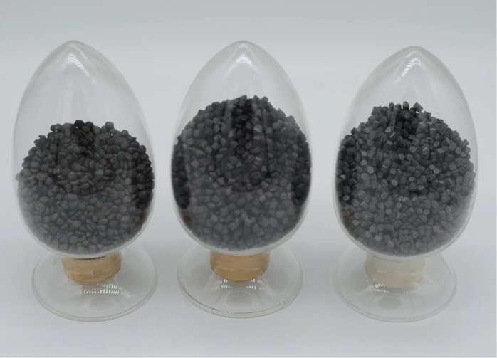
Injection molded or bonded magnets can be formed as thin-wall rings, hubs, carriers, brackets, or insert-molded assemblies. This can reduce assembly steps and improve repeatability.
Practical Selection Workflow
- Confirm the working conditions: dust, oil, moisture, vibration, shock, temperature, space, and magnetic interference.
- Confirm the control requirement: absolute angle, incremental feedback, speed sensing, commutation, or multiple outputs.
- Confirm the sensing layout: shaft-end, face, radial, inner-diameter, outer-diameter, or dual-track.
- Choose the magnetic target: single-pole-pair magnet, diametric magnet, multi-pole ring, pole wheel, or custom assembly.
- Estimate pole count and pole pitch based on resolution, diameter, sensor capability, air gap, and speed.
- Select material and process.
- Validate the real assembly: field amplitude, waveform, pole balance, air-gap tolerance, runout, temperature behavior, and output quality.
If these steps are not complete, discussing “how many poles,” “how many gauss,” or “which magnet grade” too early can easily lead to the wrong design.
Conclusion
Magnetic encoders are not chosen only because they are compact or low cost. They are chosen because they can provide reliable non-contact feedback in conditions where contamination, vibration, moisture, space, and mechanical tolerance are real engineering problems.
For rotary position sensing, choose the environment first, the control requirement second, and the magnetic target design third. Only after that should the design move into pole count, ring diameter, material, air gap, magnetizing fixture, and production inspection.
Chase Technology supports magnetic encoder magnet projects from magnetic circuit review and material selection to custom tooling, magnetizing fixture design, and production quality control. For multi-pole magnetic encoder rings, early evaluation of sensor position, air gap, runout, pole pitch, and waveform quality can reduce debugging risk before mass production.
FAQ
Why are magnetic encoders suitable for dusty or oily environments?
Magnetic encoders read magnetic field changes instead of relying on a clean optical path. Dust, oil, water vapor, and many non-ferrous contaminants are less likely to block the sensing principle, especially when the encoder structure is properly sealed.
Are magnetic encoders more accurate than optical encoders?
Not necessarily. Optical encoders often have advantages in very high resolution and precision applications. Magnetic encoders are usually selected for robustness, compact structure, contamination tolerance, vibration resistance, and cost-effective integration.
Is a multi-pole magnetic ring always better than a single-pole magnet?
No. A single-pole-pair or diametric magnet is often suitable for 360-degree absolute angle sensing. A multi-pole magnetic ring is better when the system needs repeated magnetic cycles for speed feedback, incremental feedback, or higher pulse counts.
How many poles should a magnetic encoder ring have?
The pole count depends on target resolution, sensing-track diameter, sensor IC capability, air gap, speed, runout, and magnetizing quality. Higher pole count can improve pulse count, but it also makes the design more sensitive to pole pitch and mechanical tolerance.
What is the most common mistake in magnetic encoder magnet selection?
The most common mistake is choosing the magnet by surface field strength or pole count before confirming the real air gap, sensor position, runout, output requirement, and waveform quality after final assembly.