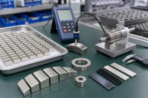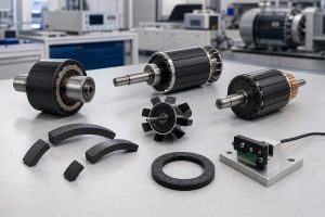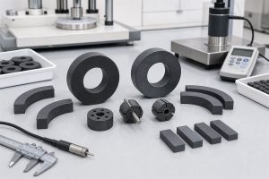


Sensor assemblies are becoming smaller, more integrated, and more demanding. A magnetic target may need to sit on a shaft, inside a molded housing, around a hub, or next to a sensor IC with a tightly controlled air gap. In these applications, the magnet is not just a separate part. It is part of a functional magnetic assembly.
Injection molded magnets are useful because they allow magnetic material, polymer structure, metal inserts, hubs, carriers, and sensing targets to be designed together. For permanent magnet sensors, Hall effect sensors, magnetic angle sensors, encoder rings, gear position sensors, and compact motor feedback systems, overmolding and insert molding can reduce assembly steps while improving repeatability.
This article explains how injection molded magnets are used in overmolded and insert molded sensor assemblies, what engineers should specify, and how to validate the magnetic performance before production.

What Are Injection Molded Magnets?
Injection molded magnets are produced by mixing magnetic powder with a thermoplastic binder and processing the compound through an injection molding machine. Common magnetic powders include ferrite, NdFeB, and SmFeN. Common binders include PA6, PA12, PPS, and other engineering polymers selected according to temperature, chemical exposure, strength, and dimensional stability.
Unlike many sintered magnets, injection molded magnets can be formed into complex shapes with integrated mechanical features. They can also be molded around inserts, shafts, sleeves, brackets, or plastic carriers. After molding, the part can be magnetized with the required pole pattern using a matched magnetizing fixture.
Chase Technology applies this process in custom injection molded magnets, permanent magnet sensor components, micro motor magnetic assemblies, water pump rotors, and other application-specific magnetic parts.
Overmolding vs Insert Molding: What Is the Difference?
In sensor magnetic assemblies, overmolding and insert molding are closely related, but the design focus is slightly different.
Overmolding
Overmolding means molding one material over or around an existing part. In a magnetic assembly, the molded magnetic compound may cover a carrier, hub, metal shaft, plastic support, or another functional structure. The goal is often to lock the magnet into a defined position, protect the assembly, and reduce later bonding or manual placement.
Insert Molding
Insert molding means placing an insert into the mold before injection, then molding the magnetic compound or plastic structure around it. The insert may be a metal shaft, bushing, sleeve, pin, bracket, sensor carrier, or rotor core. The key is that the insert must stay in position during molding and remain mechanically locked during use.
For sensor assemblies, both methods are valuable because they define the relationship between the magnet, mechanical datum, and sensor position. That relationship often matters more than the surface gauss of the magnet alone.
Why Sensor Assemblies Benefit from Molded Magnetic Integration
Traditional sensor assemblies often rely on a separate magnet that is glued, pressed, or clipped into place. That can work for simple products, but it creates risks in compact or high-volume designs.
Common problems include:
- Magnet position tolerance stacking up with housing and shaft tolerance
- Air gap drift between the magnet and sensor IC
- Adhesive thickness variation
- Magnet rotation or axial movement during operation
- Manual assembly variation between operators or batches
- Difficulty maintaining pole alignment or waveform consistency
Injection molded magnetic assemblies reduce these risks by integrating the magnet into the part geometry. The molded component can control location, retention, pole pattern, and sensing distance more consistently than a loose magnet assembled late in the process.
Typical Sensor Applications
Overmolded and insert molded magnets are especially useful when the magnetic target must be positioned repeatably relative to a sensor IC. Typical applications include:
- Angle sensor magnets for rotary position feedback
- Gear position sensor magnetic targets for automotive systems
- Robot joint sensor rings and multi-pole magnetic disks
- Car sunroof sensor components for automotive comfort systems
- Pump rotor sensor targets and micro motor position feedback components
- Hall effect sensor magnets and magnetic encoder rings
In each case, the magnet must be designed around the sensor location, not only around magnet size.
Design the Sensor Magnetic Assembly as a System
A molded sensor magnet assembly has several functions at once: magnetic signal generation, mechanical positioning, insert retention, environmental protection, and production repeatability. These functions should be designed together from the beginning.
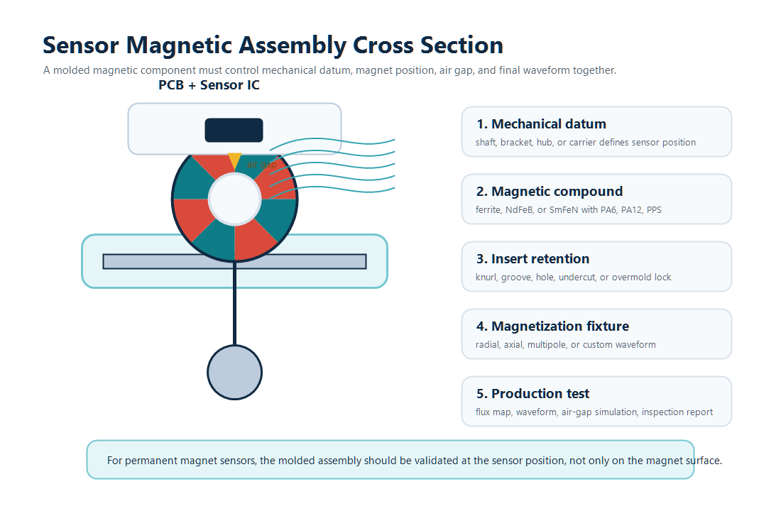
The key system-level questions are:
- Where is the sensor IC located?
- What is the nominal air gap and maximum tolerance?
- What magnetic field range does the sensor need?
- Is the signal based on angle, speed, index, position, or pole transitions?
- Does the part rotate, slide, vibrate, or contact fluid?
- Will the magnet be molded around a metal insert, plastic carrier, hub, shaft, or bracket?
- How will the part be magnetized and inspected in production?
If the assembly is designed only around the magnet drawing, important sensor-level requirements can be missed.
Material Selection for Insert Molded Sensor Magnets
Material selection depends on magnetic output, environmental exposure, part geometry, operating temperature, and molding requirements.
| Material System | Typical Fit | Design Notes |
|---|---|---|
| Injection molded ferrite | High-volume sensor targets, appliance sensors, pump rotor magnets, automotive position components | Cost-effective, corrosion resistant, and suitable for complex geometry, but lower magnetic output than rare-earth compounds. |
| Injection molded NdFeB | Compact sensor assemblies that need stronger magnetic output | Useful when space is limited. Temperature, corrosion, and binder selection should be reviewed carefully. |
| Injection molded SmFeN | Precision molded sensor components needing rare-earth performance and environmental stability | Good candidate when corrosion resistance, molding integration, and stable magnetic output are important. |
| Non-magnetic overmold plus magnet insert | Assemblies where the magnet is separate but locked into a carrier or housing | Can protect and locate the magnet, but the interface and magnet movement risk must be controlled. |
The binder is just as important as the magnetic powder. PA6, PA12, PPS, and other materials have different temperature resistance, flow behavior, moisture behavior, toughness, and dimensional stability. Chase’s R&D and material development capabilities are relevant when the project needs a tailored magnetic compound rather than an off-the-shelf magnet.
Insert Retention: Preventing Movement After Molding
Insert molding is only reliable when the insert remains locked in position during molding and during the product lifetime. A smooth metal shaft or sleeve may not provide enough mechanical retention by itself.
Common retention features include:
- Knurling or surface roughening
- Grooves, holes, and undercuts
- Shoulders, steps, or flanges
- Mechanical interlock between molded material and insert
- Surface treatment to improve bonding or corrosion resistance
- Dimensional features that prevent axial movement and rotation
Insert retention should be reviewed together with mold flow. High injection pressure, magnetic powder loading, and compound viscosity can move the insert if the fixture and mold are not designed correctly.
Mold Flow and Tooling Considerations
Injection molded magnetic compounds do not behave exactly like ordinary plastics. Magnetic powder loading affects flow, shrinkage, mechanical strength, and surface quality. Tooling decisions therefore influence both the mechanical part and the magnetic performance.
Important tooling questions include:
- Where should the gate be placed to avoid voids or weak areas?
- How will the insert be held during injection?
- Will magnetic powder orientation or flow direction affect performance?
- How much shrinkage must be allowed around the insert?
- Can the part be demolded without stressing the magnetic section?
- How will cavities be balanced in high-volume production?
This is where in-house tool making and fixture design become important. The mold, insert fixture, and later magnetizing fixture all need to support the same functional requirement.
Magnetization Must Be Designed with the Assembly
Molding creates the shape. Magnetization creates the signal. For sensor assemblies, the magnetization pattern must match the sensor location and algorithm.
Examples include:
- Diametric magnetization for angle sensing
- Radial or axial magnetization for ring-shaped targets
- Multi-pole magnetization for encoder rings and speed sensing
- Custom pole patterns for index or reference signals
- Dual-track patterns for more advanced position systems
The magnetizing fixture should be designed early, not after the molded part is finalized. If the geometry cannot be magnetized cleanly, the sensor waveform may be weak, asymmetric, or difficult to control in production.
Validation: Test at the Sensor Position
For sensor assemblies, surface magnetic field measurement is useful, but it is not enough. The final test should confirm that the sensor receives the correct field at the real air gap and real sensing position.
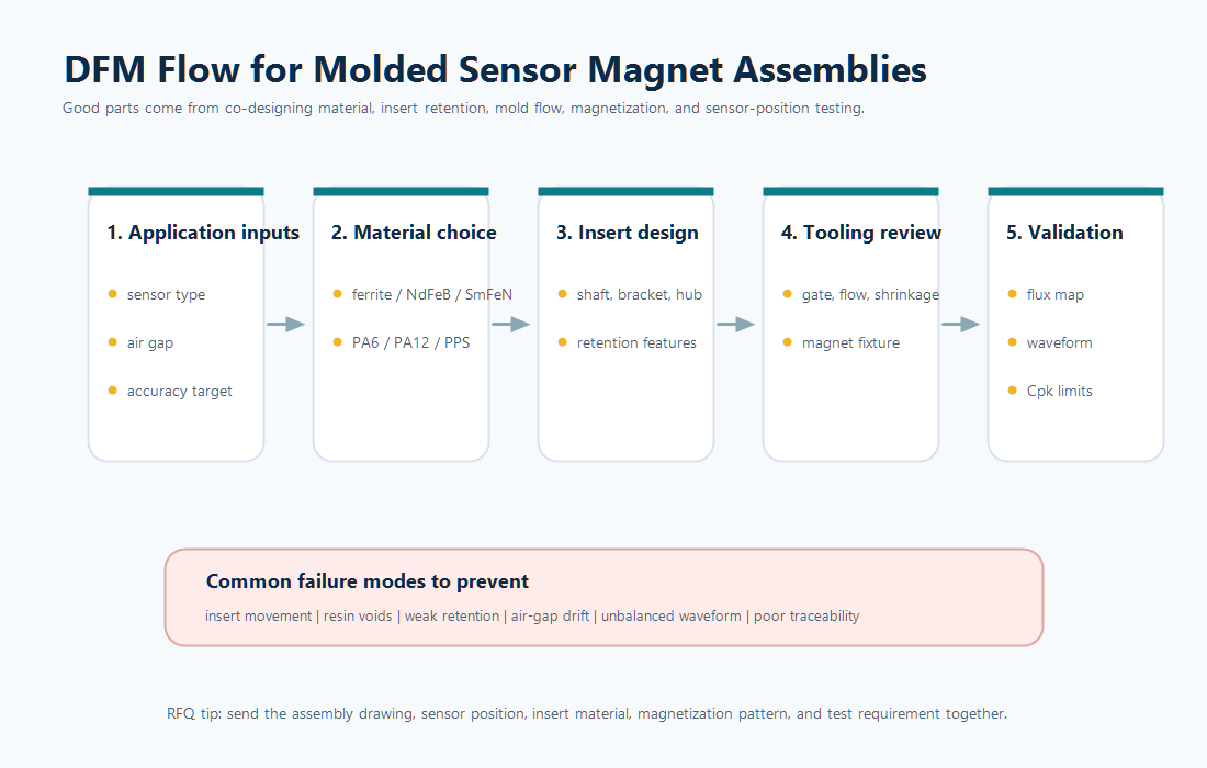
Recommended validation items include:
- Dimensional inspection of insert position and molded geometry
- Concentricity, runout, and air-gap verification
- Surface flux mapping and sensor-position flux measurement
- Waveform inspection for multi-pole or angle sensor components
- Insert pull-out, torque, or retention testing when required
- Thermal cycling, humidity, vibration, and chemical exposure tests
- Batch-to-batch comparison and production control limits
For critical programs, Chase can support magnetic simulation before tooling and quality control during production.
When Overmolding or Insert Molding Is the Better Choice
Overmolding or insert molding is usually worth considering when the sensor assembly has one or more of these requirements:
- The magnet must be precisely located relative to a shaft, bracket, or sensor IC
- The product needs fewer manual assembly steps
- The air gap is small or sensitive to tolerance stack-up
- The magnet needs protection from movement, vibration, fluid, or handling damage
- The assembly requires custom magnetization after molding
- The part is used in high-volume production where repeatability matters
For simple low-volume products, a separate magnet may be enough. For compact sensor modules, automotive sensor parts, pump rotors, and micro motor assemblies, molded magnetic integration often provides a more stable production route.
Conclusion
Injection molded magnets are especially valuable in sensor assemblies because they allow the magnetic target, insert, hub, carrier, and sensing geometry to be designed as one repeatable component. Overmolding and insert molding can reduce assembly variation, improve air-gap control, support custom magnetization, and make high-volume production more stable.
For permanent magnet sensors, magnetic angle sensors, encoder rings, pump rotors, micro motors, and other compact magnetic assemblies, the best design starts with the sensor requirement and works backward to material, insert retention, tooling, magnetization, and production inspection.
FAQ
What is an injection molded magnet?
An injection molded magnet is made by mixing magnetic powder with a thermoplastic binder and molding the compound into a functional shape. It can form complex geometries and can be magnetized after molding with a custom pole pattern.
Why use overmolding for sensor magnets?
Overmolding can lock the magnet into a defined position, protect the assembly, reduce manual assembly steps, and help control the air gap between the magnet and sensor IC.
What is insert molding in a magnetic sensor assembly?
Insert molding places a metal or plastic insert into the mold before injection. The magnetic compound or plastic structure is then molded around the insert, creating a mechanically integrated magnetic component.
Which materials are used for injection molded sensor magnets?
Common material systems include injection molded ferrite, injection molded NdFeB, and injection molded SmFeN with binders such as PA6, PA12, or PPS. The best choice depends on field strength, temperature, corrosion exposure, geometry, and cost.
How should molded sensor magnet assemblies be tested?
They should be tested at the assembly level, including insert position, air gap, surface flux, sensor-position flux, waveform, retention strength, temperature behavior, and batch-to-batch consistency.