

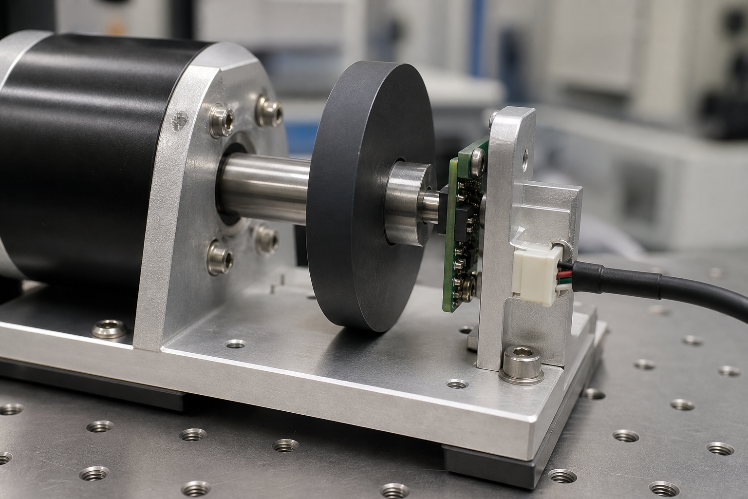
Your magnetic position sensor is only as good as the magnet driving it. The sensor IC itself might be calibrated to sub-degree precision in the factory, but once you pair it with a real magnet in a real mechanical assembly, geometry takes over. The shape of that magnet, such as its diameter, thickness, profile, and pole configuration, directly controls how the magnetic field distributes across the sensing area. Get it wrong, and you’re chasing accuracy problems that no amount of firmware can fix.
At Chase Technology, we’ve seen this play out across hundreds of sensor projects in automotive, industrial, and consumer applications. Here’s what we’ve learned about matching magnet geometry to position-sensing requirements.

Why Geometry Matters More Than Raw Strength
Most engineers default to picking the strongest magnet they can find. But here’s the thing: a magnetic position sensor doesn’t need brute force. It needs a predictable, uniform field within its operating window.
You need the right field shape, not just more teslas. Think of it this way: a magnet’s geometry acts like a lens that focuses field lines. A ring, arc, or multi-pole shape produces a radically different flux distribution than a simple block. The right shape concentrates the field exactly where the Hall element or magnetoresistive sensor sits, while minimizing stray interference elsewhere.
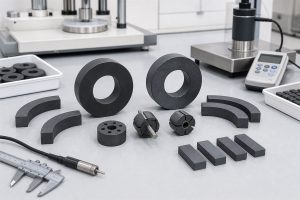
Common Magnet Shapes and Their Sensing Characteristics
Not all shapes perform equally in position detection. Here’s a quick comparison:
|
Magnet Shape |
Best For |
Key Advantage |
Typical Limitation |
|
Diametric Disc/Cylinder |
On-axis rotary angle sensing |
Uniform in-plane field at center |
Sensitive to tilt and eccentricity |
|
Ring (Multipole) |
Off-axis or through-shaft rotation |
Allows shaft pass-through, scalable pole count |
Requires tight concentricity tolerances |
|
Arc Segment |
Partial-rotation or limited-angle |
High field at specific zone |
Field uniformity drops at segment edges |
|
Bar/Block |
Slide-by linear position |
Simple mounting, easy sourcing |
Cornering effect limits close-range accuracy |
The automotive sector alone has over 100 magnetic position sensor applications, ranging from throttle bodies and brake pedals to steering angle detection, and each one demands a different geometry-performance trade-off.
The Diameter-to-Thickness Ratio Problem
Here’s something that often gets overlooked. For linear slide-by sensing, the ratio of a magnet’s thickness to its diameter directly controls how close the sensor can get before the field becomes distorted.
According to research from TI, increasing a cylindrical magnet’s thickness from 4 mm to 8 mm reduces the “cornering effect,” which is that unwanted nonlinearity you see when the sensor is too close to the magnet’s edge. But it also shifts the field magnitude. So you’re always balancing proximity, linearity, and signal strength.
In our experience at Chase, we recommend running finite-element simulations before committing to a geometry. We use magnetic simulation tools in-house to model flux density across the full stroke or rotation angle, so our customers can see exactly where distortion kicks in before cutting steel for a mold.
Multipole Rings: Precision Through Pole Count
For rotary speed and angular position applications, such as BLDC motor commutation or ABS wheel-speed sensors, multipole ring magnets are the standard. The number of poles, their width, and the transition sharpness between north and south all affect signal quality.
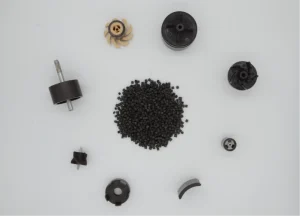
Injection-molded magnets have a real edge here. Because we can orient magnetic particles during the molding process, we’re able to create 24, 32, or even higher pole counts with smooth transitions and consistent amplitude. That’s much harder (and more expensive) to achieve by grinding and magnetizing sintered segments.
The polymer matrix in injection-molded rings also provides built-in vibration damping and corrosion resistance—two things that matter a lot in automotive underbody or industrial servo applications where sensors live for 10+ years.
Why Manufacturing Tolerance Is a Hidden Accuracy Killer
A 2026 study on off-axis magnetic ring sensors found that manufacturing errors degraded accuracy from the ideal ±0.38° to ±1.7°. These errors include local deviations in magnetization, eccentricity relative to the shaft, and misalignment during magnetization, resulting in a 4.5× loss in precision purely from production variability.
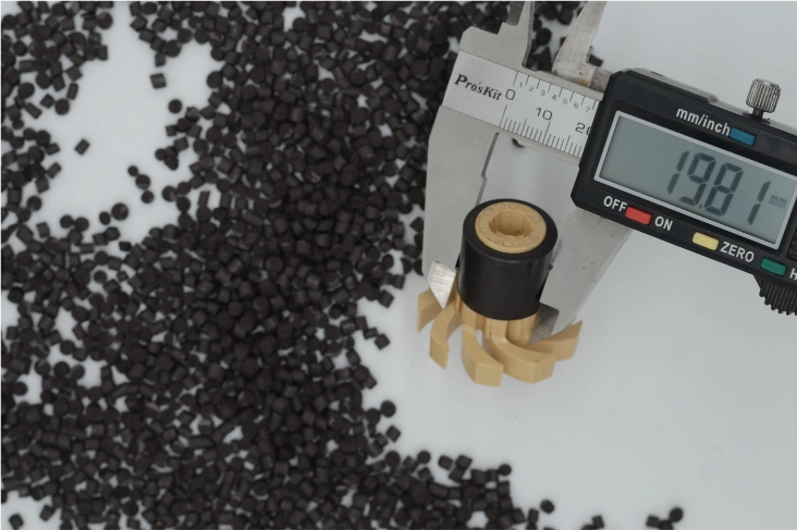
This is exactly why we invest heavily in tooling precision and quality control at Chase. Our injection molding process produces near-net-shape parts with tight dimensional tolerances right out of the mold, eliminating the need for secondary grinding. Consistent geometry means consistent magnetic performance from piece to piece, which directly translates to consistent sensor output across a production run of thousands or millions of units.
Choosing the Right Magnet Shape for Your Sensor
So how do you pick? Start with these questions:
- What motion type? Rotary → disc or ring. Linear → bar or block.
- Shaft access? Through-shaft → ring. End-of-shaft → disc.
- Pole count needed? Single dipole for angle sensing. Multipole for speed or incremental position.
- Space constraints? Tight packaging often demands injection-molded custom shapes that combine the magnet with structural features like gears or housings.
- Production volume? High volume (100k+ pieces/year) strongly favors injection molding for cost and consistency.
Key Takeaways
The magnet in a magnetic position sensor isn’t just a field source, but a precision component that defines your system’s accuracy ceiling. Shape determines flux distribution. Tolerances determine repeatability. And the manufacturing method determines whether you can hold both at scale.
Whether you are designing a new position-sensing system or troubleshooting accuracy problems in an existing one, we encourage you to look at the magnet geometry first. In many cases, switching from a generic off-the-shelf block to a custom-shaped injection-molded or compression-bonded magnet can cut position error by 50% or more without changing anything else in your system.
FAQs
What magnet shape is best for rotary position sensors?
For on-axis angle measurement, a diametrically magnetized disc or cylinder works well. For through-shaft or off-axis configurations, a multipole ring is typically the better choice. The right answer depends on your air gap, required accuracy, and mechanical layout.
Does a stronger magnet always mean better sensor performance?
No. Sensor ICs have a defined input range (often 20–80 mT). A magnet that’s too strong saturates the sensor and creates errors. What matters more is delivering a uniform, predictable field at the sensing location—and that’s a geometry problem, not a strength problem.
Why use injection molded magnets instead of sintered magnets for sensors?
Injection molded magnets offer tighter dimensional tolerances, complex shape capability, built-in corrosion resistance, and lower per-piece cost at high volumes. While sintered magnets are stronger, many sensor applications don’t need maximum field strength; they need geometric precision and consistency.
How does air gap affect magnet shape selection?
Larger air gaps reduce field strength and smooth out non-uniformities, but also reduce signal-to-noise ratio. A thicker or larger-diameter magnet can compensate, but that increases cost and weight. Simulation helps find the minimum magnet size that meets your signal requirements at the actual working air gap.
Can Chase Technology help with magnet design for custom sensors?
Yes. We provide application-driven magnetic design support including FEM simulation, prototyping, and high-volume production of injection-molded, compression-bonded, and sintered magnets.