

Compression molded magnets and injection molded magnets are both bonded magnet technologies. They combine magnetic powder with a polymer binder, then form the compound into a finished magnetic part. For OEM engineers, however, the two processes are not interchangeable. They make different tradeoffs in magnetic strength, shape freedom, mechanical integration, tooling investment, and total assembly cost.
The right choice depends on what the finished component must do. A simple ring that needs higher magnetic loading may favor compression molding. A sensor target, motor rotor, pump rotor, or magnetic assembly with shafts, hubs, thin walls, or insert features may favor injection molding. The important question is not only which magnet material is stronger, but which process creates the most reliable magnetic assembly for production.
This guide compares compression molded magnets and injection molded magnets from the viewpoint of custom magnetic components, micro motor rotors, water pump rotors, permanent magnet sensors, and other OEM assemblies.
What Are Bonded Magnets?
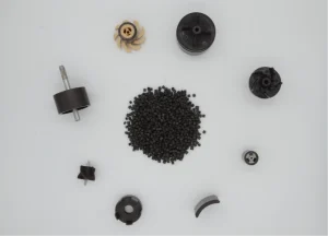
Bonded magnets are produced by mixing magnetic powder with a polymer binder. The powder may be ferrite, NdFeB, SmFeN, or another application-specific magnetic material. The binder may be PA6, PA12, PPS, epoxy, or another resin system selected for temperature, strength, chemical exposure, and dimensional stability.
Compared with sintered magnets, bonded magnets usually have lower maximum magnetic energy density. Their advantage is manufacturability. They can be made into shapes, tolerances, and integrated structures that would be difficult or expensive with brittle sintered magnets.
How Compression Molded Magnets Are Made
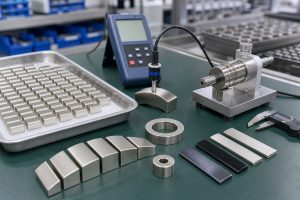
Compression molded magnets are made by placing a measured magnetic compound into a mold cavity, then applying pressure and heat to form a compact part. The process is well suited to simple or moderately complex geometries such as rings, disks, blocks, plates, and arc segments.
Because the material does not need to flow through long injection paths, compression molding can often support higher magnetic powder loading than injection molding. Higher powder loading can improve magnetic output, especially when the shape is compact and the application needs more flux from a limited volume.
Where Compression Molded Magnets Fit Best
- Rings, disks, blocks, plates, and simple arc magnet shapes
- Bonded NdFeB or ferrite parts requiring higher magnetic loading
- Compact components where magnetic output is more important than complex 3D geometry
- Applications that can accept secondary assembly, bonding, or machining if required
- Programs where tooling cost and stable part geometry must be balanced carefully
Compression molding can be a strong option when the magnet is a functional insert or ring rather than a fully integrated molded assembly. For example, a bonded ring magnet used in a rotor or sensor may be compression molded first, then assembled into a housing or carrier later.

How Injection Molded Magnets Are Made
Injection molded magnets are produced by feeding magnetic compound into an injection molding machine and injecting it into a mold cavity. The magnetic compound must flow through runners, gates, and thin sections before cooling into the final shape.
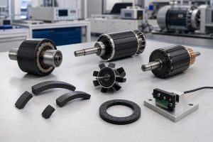
This flow requirement usually limits the maximum magnetic powder loading compared with compression molding. However, injection molding can create much more complex geometry. It can form thin walls, hubs, gears, shafts, holes, slots, positioning features, and integrated mounting structures. It can also be used for overmolding and insert molding around metal or plastic components.
That makes injection molding especially useful when the magnet is part of a larger functional assembly rather than a standalone magnetic piece.
Where Injection Molded Magnets Fit Best
- Sensor magnets that must control the relationship between magnet, housing, and sensor IC
- Magnetic encoder rings with custom pole patterns and stable mechanical datums
- Micro motor rotors and permanent magnet rotors with integrated hubs or shafts
- Water pump rotors where magnet, impeller, sleeve, and shaft position are related
- High-volume parts where reduced assembly steps offset tooling investment

Strength: Magnetic Strength vs Mechanical Strength
When engineers compare magnet strength, they often mean magnetic output. But in an OEM magnetic assembly, strength can mean several different things:
- Magnetic flux density at a target distance
- Magnetic waveform accuracy after magnetization
- Mechanical strength of the molded part
- Retention strength around an insert, shaft, or hub
- Thermal stability and resistance to demagnetization
Compression molded magnets can often achieve higher magnetic powder loading, which may improve magnetic output for the same volume. If the application is a simple ring, block, or disk where the part does not require complex molded features, compression molding may provide a stronger magnetic result.
Injection molded magnets may have lower magnetic loading, but they can be stronger at the assembly level. A molded rotor can lock the magnet geometry to a shaft or hub. A molded sensor target can control air gap and angular alignment. A molded pump rotor can reduce separate bonding operations. In those cases, the magnetic material alone may be slightly less strong, but the finished component can be more repeatable and robust.
Shape: Simple High-Loading Parts vs Complex Magnetic Assemblies
Shape freedom is one of the biggest differences between the two processes.
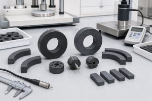
- Compression molding is best when the part geometry is relatively straightforward. It works well for rings, disks, blocks, plates, and arc segments. These shapes can be highly useful in motors, sensors, and industrial assemblies, especially when the magnetic requirement is clear and the mechanical interface is handled by another component.
- Injection molding is the better choice when the magnet must become part of the mechanical design. It can create ribs, holes, undercuts, thin walls, overmolded structures, insert-molded shafts, and custom features that help with assembly. It can also reduce tolerance stack-up because the magnetic feature and mechanical datum are formed in the same tool.
For permanent magnet sensors, this is often decisive. A magnet that is stronger on paper may still fail if its position relative to the sensor IC is unstable. A slightly lower-output injection molded magnetic component may perform better if it controls the sensing distance and pole alignment more consistently.
Cost: Part Price Is Not the Whole Cost
The cost comparison between compression molded magnets and injection molded magnets depends on volume, material, tooling, tolerance, post-processing, and assembly design. A low piece price does not always mean low system cost.
- Compression molded magnets may be cost-effective when the part is simple, magnetic loading is important, and secondary assembly is acceptable. Tooling may be less complex for simple shapes. Material use can be efficient. But additional steps such as bonding, positioning, grinding, coating, inspection, or fixture assembly may still add cost.
- Injection molded magnets usually require more careful tooling and process development. The upfront cost can be higher, especially when insert molding, mold flow, magnetizing fixtures, and dimensional validation are involved. But injection molding can reduce downstream assembly cost by combining several functions into one molded part.
For high-volume OEM programs, the winning process is often the one that lowers total landed cost: fewer parts, fewer manual steps, fewer quality escapes, and more stable assembly performance.
Comparison Table
| Decision Factor | Compression Molded Magnets | Injection Molded Magnets |
|---|---|---|
| Magnetic loading | Often higher because the compound does not need long flow paths | Usually lower because the material must flow during injection |
| Magnetic output | Strong for compact rings, disks, blocks, and arcs | Good when output is balanced with shape and assembly integration |
| Shape freedom | Best for simple or moderate shapes | Excellent for complex 3D geometry, thin features, and molded details |
| Insert molding | Limited; secondary assembly is more common | Strong advantage for shafts, hubs, carriers, sleeves, and brackets |
| Mechanical integration | Often needs bonding, pressing, or carrier assembly | Can combine magnetic and mechanical functions in one molded part |
| Tooling cost | Can be efficient for simple stable shapes | Higher for complex tools, but may reduce total assembly cost |
| Best-fit applications | Rings, disks, blocks, arc magnets, high-loading bonded magnets | Sensor magnets, encoder rings, motor rotors, pump rotors, custom assemblies |
Application Examples
Micro Motor Rotor Magnets
For a simple rotor ring, compression molding may be attractive if magnetic output is the main priority. For a rotor that needs a shaft, hub, sleeve, or balancing feature integrated into the magnetic component, injection molding may be better. The final choice should consider magnetic waveform, rotor balance, temperature, speed, and assembly process.
Water Pump Rotors
In a water pump rotor, the magnet is rarely isolated from the mechanical design. The rotor may need to work with an impeller, shaft, sleeve, bearing, and fluid environment. Injection molded magnets are often valuable because they can integrate magnetic and mechanical functions. Compression molded magnets can still be useful when the magnetic ring is assembled into a separate rotor structure.
Permanent Magnet Sensors
For angle sensors, Hall effect sensors, gear position sensors, and magnetic encoder targets, the key requirement is stable sensing performance. Injection molding is often preferred when the magnetic target must align with a housing, shaft, or sensor IC. Compression molding can be a good choice when the sensor target is a simple disk or ring and the mechanical datum is controlled elsewhere.
Custom Magnetic Assemblies
In many OEM projects, the best result comes from designing the magnet, insert, carrier, magnetization pattern, and inspection method together. Chase Technology often evaluates these programs as magnetic assemblies rather than isolated magnet drawings.
Which Process Should You Choose?
Choose compression molded magnets when the part shape is simple, magnetic loading is important, and secondary assembly is acceptable. Choose injection molded magnets when the part requires complex geometry, insert molding, overmolding, tight mechanical datums, or reduced assembly steps.
For many custom magnetic components, the decision is not final until the assembly requirement is clear. A bonded magnet should be specified by its working function: flux at the target location, mechanical interface, operating temperature, production tolerance, and validation method.
Chase Technology can support both process selection and custom magnetic assembly development for your requirements.
FAQ
Are compression molded magnets stronger than injection molded magnets?
Compression molded magnets can often achieve higher magnetic powder loading, so they may provide stronger magnetic output in simple compact shapes. Injection molded magnets may be stronger at the assembly level when they integrate shafts, hubs, inserts, or sensing datums.
When should I choose injection molded magnets?
Choose injection molded magnets when the part needs complex geometry, thin features, insert molding, overmolding, or high-volume assembly integration. They are often used for sensor magnets, encoder rings, motor rotors, and pump rotor components.
When should I choose compression molded magnets?
Choose compression molded magnets when the part is a ring, disk, block, plate, or arc magnet that needs higher magnetic loading and does not require complex molded features. They are useful when magnetic output per volume is a key requirement.
Which process is lower cost?
It depends on the total system cost. Compression molding can be economical for simple parts. Injection molding can reduce cost in high-volume assemblies by combining magnetic and mechanical features and reducing secondary assembly steps.
Can both processes use ferrite or NdFeB powder?
Yes. Both processes can use bonded ferrite or bonded NdFeB systems, depending on the binder and production method. The right choice depends on magnetic output, temperature, cost, corrosion behavior, and finished assembly design.