

Why do top cable designers rely on injection molding for magnetic connectors? Simple: it turns separate magnets, pins, and wires into a tough, seamless final product.
Magnetic charging relies on perfect alignment to work right every time. Injection molding gives you tight tolerances, built-in strain relief, and water resistance all in one repeatable process. Let’s look at why it is the best fit for your next cable project.
What Is a Custom Magnetic Cable?
A custom magnetic cable connects its cable head to a matching tip, socket, or dock through magnetic attraction. Many designs also use pogo pins, contact rings, a small PCB, or a steel flux-return part.
You will see these cables in electronics, wearables, medical products, appliances, test equipment, sensors, and charging docks. Inside the small head, electrical, magnetic, mechanical, and cosmetic requirements compete for space.
There are two molding jobs to consider. A supplier may mold a bonded magnetic component. It may instead overmold a separate sintered magnet, connector, and cable. Some projects use both.
Why Injection Molding Fits Magnetic Cable Design
Precise Magnet and Contact Alignment
The magnet, contacts, and mating face must share a controlled centerline. A high magnet can keep contacts open. A sideways shift can feel weak or crooked. One mold can locate all features from the same datum.
Molded ribs, stops, pockets, and polarity keys reduce variation. They can prevent reverse mating or rotation while keeping contact pressure consistent.
Fewer Parts and Assembly Steps
A connector may need a magnet, carrier, shell, spacer, adhesive, and cable boot. Insert molding can combine several parts. Molded locks may replace glue in selected areas.
Part consolidation cuts labor and removes interfaces that can loosen, leak, or shift. It also simplifies the bill of materials.
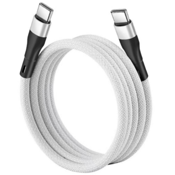
Built-In Cable Strain Relief
The cable exit is a common failure point. Molding can create a tapered boot, flexible ribs, and a controlled bend radius where the cable meets the rigid connector.
A two-material design can use a rigid carrier and softer overmold. Adhesion and shrinkage must be compatible. Validate the profile with bend and pull tests.
Better Sealing Around Inserts
Overmolding can close gaps around the cable, contact carrier, and insert. This supports resistance to dust, sweat, splash, and cleaning fluids.
Molding alone does not guarantee waterproofing. Poor adhesion, insert movement, voids, and parting lines can create leaks. Test the assembly under real conditions.
More Freedom for Custom Shapes
Molding can create curves, thin walls, logos, grip textures, light windows, indexing features, and device-specific mating faces. That helps the connector fit a tight industrial design.
The same freedom applies to an injection-molded magnetic component. Bonded ferrite, NdFeB, or SmFeN can form features that are difficult to machine into a brittle sintered magnet.
Repeatable High-Volume Production
Once the process is stable, each cavity repeats the same critical geometry. Automated loading controls orientation and cycle time. Cavity identification supports traceability.
Tooling adds upfront cost, so molding is not always best for prototypes. It pays off when a custom assembly has several parts and enough production volume.
Injection-Molded or Sintered Cable Magnets?
Many charging cables use sintered NdFeB because it provides high attraction in little space. The magnet sits in a molded carrier or overmolded connector. This suits force-sensitive designs.
A bonded magnet has lower output per volume. In return, it offers tougher edges, locating features, good consistency, and less dependence on coating. It may combine magnetic function and carrier geometry.
Compare space, attraction, release force, temperature, corrosion, magnet shape, volume, and assembly. Read our sintered versus injection-molded magnet comparison for the wider tradeoffs.
How a Custom Magnetic Cable Is Molded
Define the Mating Interface
Start with the device, not the mold. Define the connection angle, attraction force, safe release force, polarity, contact layout, air gap, current, data needs, and available envelope. Set cosmetic limits and the expected number of mating cycles.
Review the Magnetic Circuit
Magnet grade alone does not set the holding force. Magnet position, steel parts, mating distance, pole direction, and housing thickness all matter. Magnetic simulation can compare layouts before tooling begins. It can also reveal stray field near sensitive electronics.
Design Inserts and Tooling
The tool must hold the cable, contacts, magnet, and any PCB securely during filling. Gate position, resin pressure, venting, shrinkage, and weld lines affect the result. Delicate plating and solder joints need protection from heat and mechanical load.
Mold, Magnetize, and Assemble
Production may include insert preparation, controlled loading, molding, cooling, trimming, magnetization, and final assembly. Post-magnetization often simplifies handling because loose inserts do not attract each other. It must be confirmed that the complete magnetic circuit can be magnetized correctly.
Validate the Finished Cable
Measure the complete cable, not only the loose magnet. Typical checks include attraction and release force, contact resistance, temperature rise, polarity, short-circuit protection, pull strength, flex life, mating life, drop, corrosion, and moisture exposure.
For charging products, also verify performance with the real device and power profile. A connector that feels good can still run hot if contacts are misaligned or contaminated. Our overview of magnetic charging safety explains the electrical side in more detail.

Why Develop Magnetic Cables With Chase?
Chase Technology supports injection-molded magnetic compounds and components, sintered magnets, insert molding, tooling, magnetic simulation, magnetization, and assembly validation. That lets our team review more than the magnet drawing. We can look at the cable connector as a working system.
Already comparing consumer cable features? See whether magnetic charging cables are a good fit. For a new OEM design, send us the connector envelope, attraction target, current, material limits, annual volume, and test requirements. Early DFM usually prevents the most expensive changes.
If you need a custom magnetic cable solution, contact us to discuss your project.
FAQs
Are Magnetic Cables Injection Molded?
Many are. The connector housing and cable strain relief are often molded around internal parts. The magnet itself may be a separate sintered insert or an injection-molded bonded magnetic component.
Can Magnets Be Overmolded Safely?
Yes, when the magnet grade, coating, mold temperature, pressure, insert fixture, and retention features are compatible. Production tests should check chipping, movement, corrosion, pull force, and magnetic performance.
Which Magnet Is Best?
Sintered NdFeB suits very small connectors needing strong attraction. Bonded NdFeB, ferrite, or SmFeN can suit complex shapes and integrated features. The best choice depends on space, force, environment, and cost.
Does Overmolding Make Cables Waterproof?
It can improve sealing, but it does not guarantee waterproof performance. Material adhesion, voids, parting lines, contacts, and repeated bending can create leak paths. Test the finished cable to the required condition.
When Does Injection Molding Pay Off?
It usually makes sense when the connector is custom, several parts can be combined, tight alignment matters, and production volume supports tooling. Very small prototype runs may use other processes first.