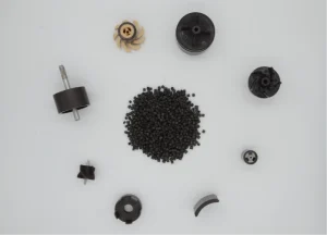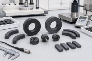


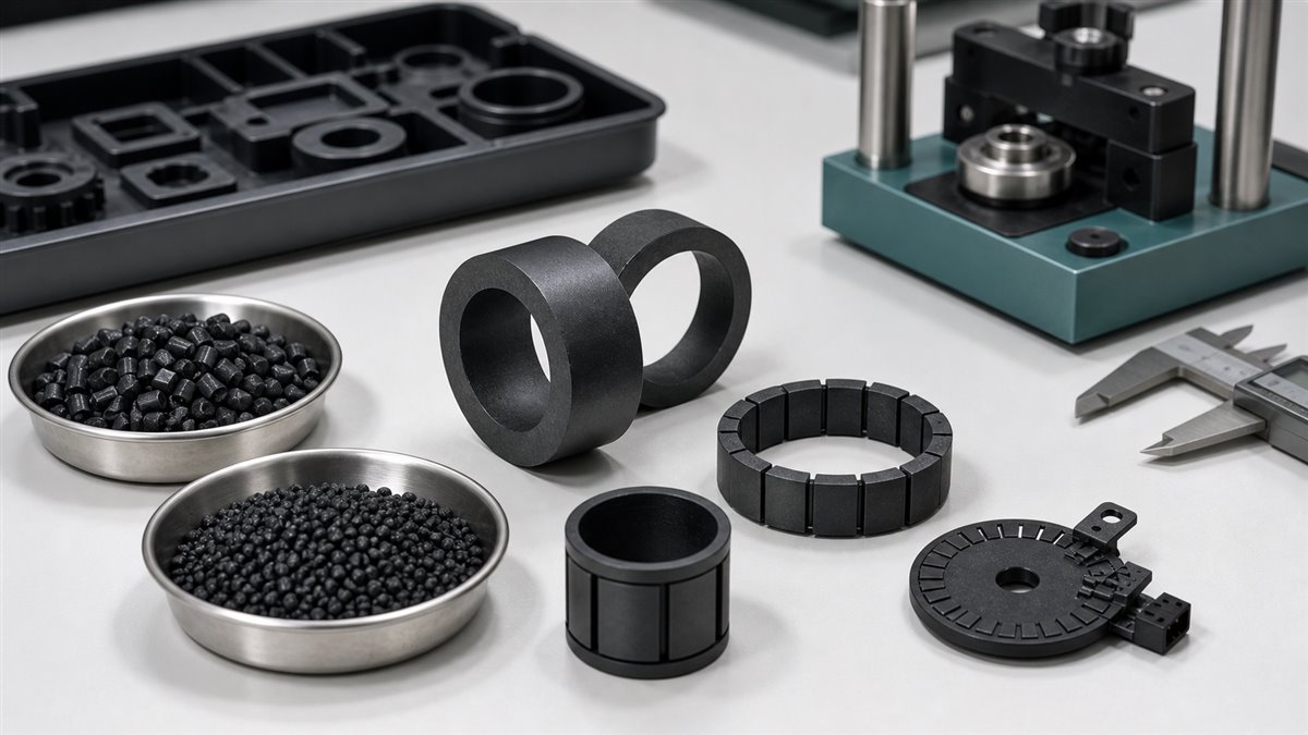
Maglastic FA19 and FB19R are both hard-ferrite bonded magnetic compound grades used for injection molded magnets. At first glance, they can look very similar. Their listed Br and maximum energy product values are close, and both are positioned for molded ferrite magnetic components. For an engineer preparing samples, however, the decision should not stop at the magnetic table.
The grade code is only the starting point. Before sampling, engineers should validate the resin system, melt flow, mechanical properties, magnetization method, tool geometry, working air gap, dimensional tolerance, and final application environment. A grade that looks equivalent in a datasheet can behave differently in a thin-wall sensor ring, a long magnetic roller, a pump rotor, or a compact motor component.
This guide compares FA19 and FB19R as sampling candidates and explains what engineers should check before moving from grade selection to molded part validation.
What Are FA19 and FB19R?
FA19 and FB19R are hard-ferrite bonded magnetic compound grades listed in the injection molded magnets grade table. They combine ferrite magnetic powder with thermoplastic resin so the compound can be molded into magnetic components with complex shapes and controlled pole patterns.
The key material difference is the resin family:
- FA19: Ferrite + PA6 compound
- FB19R: Ferrite + PA12 compound
That difference matters because the resin system affects moisture behavior, toughness, flow, molding temperature window, dimensional stability, and how the material performs in the final component. For many OEM projects, resin behavior can be just as important as magnetic output.
Published Grade Data: Useful, But Not Enough
The published hard-ferrite bonded compound table gives engineers a useful starting point. The following values are from the listed FA19 and FB19R rows and should be treated as initial comparison data, not a replacement for project-specific validation.
| Property | FA19 | FB19R |
|---|---|---|
| Composition | Ferrite + PA6 | Ferrite + PA12 |
| Br residual flux density | 284 mT / 2840 Gs | 283 mT / 2830 Gs |
| HcB coercive force | 195 kA/m / 2450 Oe | 205 kA/m / 2570 Oe |
| HcJ intrinsic coercive force | 235 kA/m / 2950 Oe | 255 kA/m / 3200 Oe |
| (BH)max maximum energy product | 15.6 kJ/m3 / 1.96 MGOe | 15.5 kJ/m3 / 1.95 MGOe |
| Mold density | 3.60 g/cm3 | 3.58 g/cm3 |
| Melt flow rate | 200 g/10 min | 100 g/10 min |
| IZOD impact strength | 19 kJ/m2 | 26 kJ/m2 |
| Tensile strength | 90 MPa | 56 MPa |
| Flexural strength | 170 MPa | 110 MPa |
The table also notes that FA and FB series MFR is tested at 270 deg C with a 10 kg load. When comparing grades, engineers should confirm the exact test method and obtain the current lot-specific datasheet before sampling.
Why Similar Magnetic Numbers Can Lead to Different Sampling Results
FA19 and FB19R have very close Br and (BH)max values. That means a simple magnetic comparison may not reveal the real selection difference. The more practical questions are:
- Will the compound fill the actual cavity geometry?
- Will it maintain dimensional stability after molding and conditioning?
- Will the part survive assembly, transport, and application stress?
- Will the magnetized waveform meet the sensor or rotor requirement?
- Will the resin system match humidity, temperature, chemical, and life-cycle conditions?
For a simple ring, FA19 and FB19R may both be candidates. For a thin-wall magnetic roller, a water-flow rotor, a high-speed motor ring, or an insert-molded sensor target, the better grade may depend on molding behavior and validation results rather than magnetic table values alone.
1. Validate the Resin System: PA6 vs PA12
The most visible difference between the two grades is the binder family. FA19 uses PA6, while FB19R uses PA12. Both are engineering polyamides, but they do not behave identically.
Before sampling, ask what the resin system means for the part:
- Moisture behavior: Will humidity exposure affect dimensions, stiffness, or magnetic assembly fit?
- Toughness: Does the part need to survive impact, snap-fit assembly, or handling stress?
- Thermal condition: Will the part see sustained heat, thermal cycling, or nearby motor temperature rise?
- Chemical contact: Will the component contact water, oil, coolant, detergent, or other fluids?
- Dimensional stability: Does the application depend on a tight air gap or low runout?
For example, a magnetic sensor ring may care most about air-gap stability and waveform repeatability. A pump rotor may care about moisture, temperature cycling, and mechanical integrity. A magnetic roller may care about straightness, length-to-diameter ratio, and uniform surface field.
2. Validate Melt Flow Before Final Tooling
MFR is not just a number in the grade table. It affects how the material fills gates, ribs, thin sections, long flow lengths, and small pole features. FA19 is listed with higher MFR than FB19R under the same FA/FB test condition, which may influence mold-filling behavior.
Before sampling, engineers should review:
- Gate type and gate position
- Flow length and thin-wall sections
- Weld line location and strength risk
- Powder orientation and possible magnetic uniformity effects
- Expected shrinkage, warpage, and roundness
- Whether the sample tool represents the production flow path
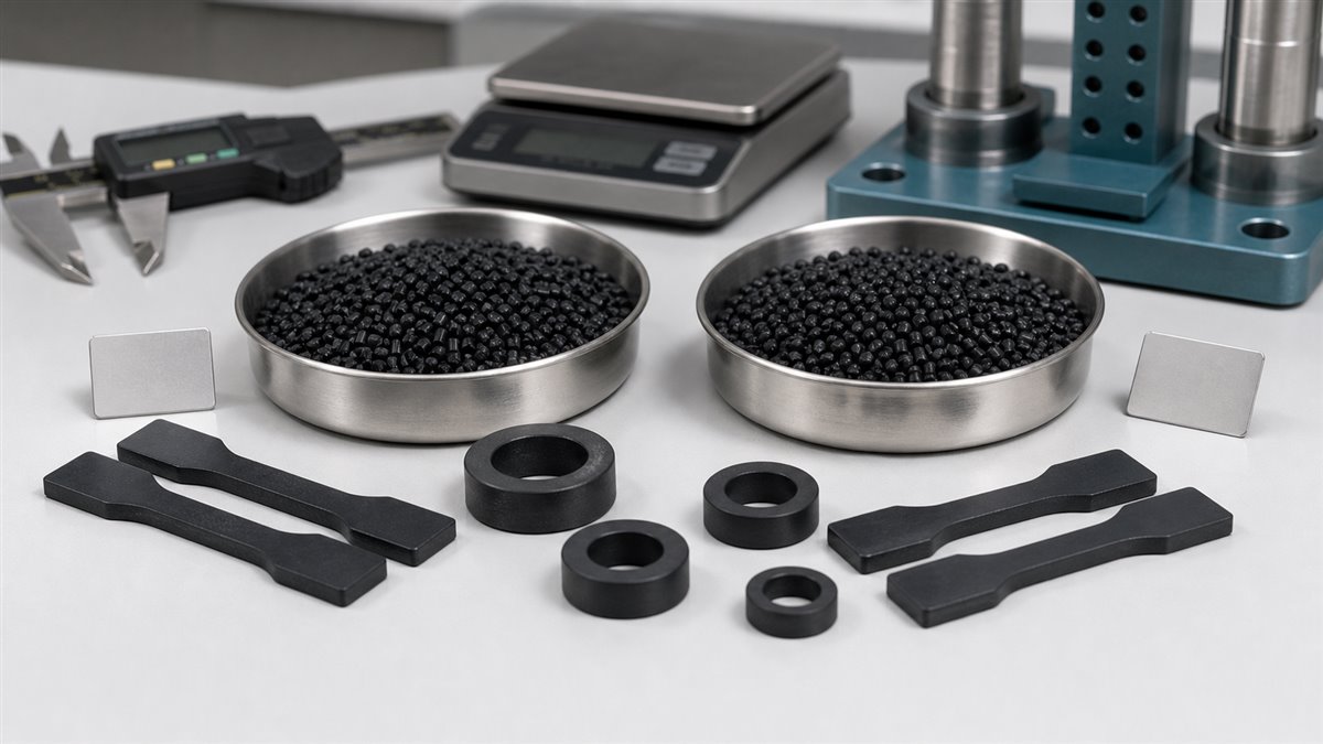
If the production component has a long, thin, or asymmetric geometry, sample plaques alone are not enough. The sample should include a geometry that represents the real cavity and critical features.
3. Validate Magnetic Output at the Working Position
For molded ferrite magnets, the table values describe material capability. The application sees the finished magnetized part. That is an important distinction.
Validation should measure the field at the actual working condition:
- Surface field map after magnetization
- Flux density at the sensor air gap
- Waveform amplitude and pole-to-pole consistency
- Radial, axial, or multi-pole magnetization pattern accuracy
- Temperature effect on signal margin
- Lot-to-lot and cavity-to-cavity variation
The Chase simulation shows an example using FA19 in an OD88 x ID76 x H35 ring with 6-pole inner-diameter magnetization and simulated surface gauss of 1250. That kind of geometry-specific result is more useful for sampling than a material table alone, because the magnetic circuit, wall thickness, and magnetization mode all affect final output.
4. Validate Mechanical Properties in the Real Part
The published table lists tensile strength, flexural strength, and impact strength. These values are helpful, but the final molded part may fail in ways that standard bars do not show.
Engineers should validate:
- Crack risk at gates, weld lines, holes, and sharp corners
- Press-fit or insert retention strength
- Torsion load if the magnet is mounted to a shaft
- Drop, vibration, and transport robustness
- Rotor balance and runout for rotating parts
- Dimensional drift after moisture or heat exposure
This is especially important when the part is not just a magnet but a functional magnetic component. Sensor targets, motor rotors, and pump rotors all combine magnetic requirements with mechanical loads.
5. Validate Magnetization Fixture Compatibility
A grade can be suitable on paper but still fail if the magnetization fixture cannot produce the required pole pattern consistently. This is common in sensor rings, encoder disks, multi-pole rotors, and small magnetic rollers.
Before sampling, define:
- Magnetization direction: radial, axial, inner diameter, outer diameter, or custom
- Number of poles and pole pitch
- Allowed pole-angle error
- Minimum and maximum field amplitude
- Measurement equipment and fixture method
- Whether the sample is magnetized in the same fixture planned for production
The magnetization method should be part of the sampling plan. Otherwise, the team may approve a molded sample that cannot be magnetized repeatably in production.
6. Validate the Application Environment
FA19 and FB19R should be evaluated in the environment where the part will actually work. Typical checks include:
- Operating temperature range and thermal shock
- Humidity exposure and moisture conditioning
- Water, coolant, detergent, oil, or other chemical exposure
- UV or outdoor exposure if applicable
- Motor heat, vibration, and centrifugal load
- Long-term signal drift in sensor applications
A PA6-based compound and a PA12-based compound may behave differently after humidity, heat, and chemical exposure. That is why sampling should include both immediate performance and conditioned performance.
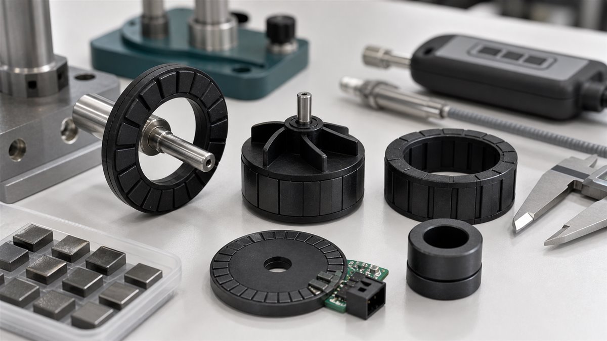
Application-Specific Sampling Notes
Magnetic Rollers and Long Parts
For long magnetic rollers, validate flow, straightness, pole uniformity, and surface field consistency along the length. The high length-to-diameter ratio can make molding and magnetization more difficult than a short ring sample.
Sensor Rings and Encoder Targets
For magnetic encoder rings, angle sensors, and gear position sensors, validate pole accuracy, signal waveform, air-gap tolerance, and concentricity. The best grade is the one that gives stable sensor output, not just a good material table value.
Pump Rotors and Flow Sensors
For pump rotors and flowmeter induction rotors, validate fluid exposure, mechanical integrity, rotor balance, and field consistency after conditioning. If the magnet is molded around a shaft or metal insert, retention testing should be part of the sample plan.
Compact Motor Components
For compact motor rotors, validate magnetic waveform, runout, balance, thermal cycling, and high-speed mechanical stability. The material grade, gate design, and magnetization fixture must work together.
FA19 vs FB19R: How to Think About the Choice
FA19 may be attractive when the design values PA6-based mechanical strength, higher listed MFR, and a good balance of ferrite magnetic performance and molded-part rigidity. FB19R may be attractive when the application benefits from a PA12-based compound, higher listed impact strength, and a different moisture or toughness profile.
But the practical answer should come from testing. The correct sampling decision is not “Which grade has the higher Br?” It is “Which grade gives the required magnetic signal, molding stability, mechanical reliability, and environmental performance in the actual part?”
Conclusion
Maglastic FA19 and FB19R are close enough in magnetic table values that engineers should avoid choosing by Br or (BH)max alone. The resin system, melt flow, toughness, dimensional stability, magnetization fixture, and application environment can change the sampling result.
Before sampling, define the real part geometry, working air gap, magnetization mode, inspection method, and conditioning tests. Then compare FA19 and FB19R as molded components, not just as rows in a grade table. That is the safest path from material screening to production-ready magnetic performance.
FAQ
What is the main difference between Maglastic FA19 and FB19R?
FA19 is listed as a Ferrite + PA6 grade, while FB19R is listed as a Ferrite + PA12 grade. Their magnetic values are close, but the resin system affects molding behavior, toughness, moisture response, and application suitability.
Are FA19 and FB19R magnetically interchangeable?
Not automatically. Their Br and (BH)max values are similar, but engineers should validate the final molded part, magnetization pattern, working air gap, dimensional stability, and environmental performance before substituting one for the other.
What should engineers test before sampling FA19 or FB19R?
Engineers should test magnetic output, melt flow behavior, molded geometry, mechanical strength, impact or assembly durability, magnetization fixture compatibility, and performance after temperature, humidity, or chemical exposure.
Why does MFR matter for ferrite bonded magnetic compounds?
MFR helps indicate flow behavior during molding. It affects gate design, filling of thin sections, weld line risk, shrinkage, and whether the sample tool represents production behavior.
Should sampling use standard test bars or real part geometry?
Both are useful, but real part geometry is essential before production approval. Sensor rings, pump rotors, and motor components should be tested in representative molded shapes and at their working magnetic positions.