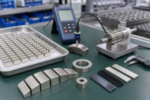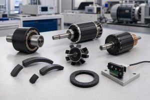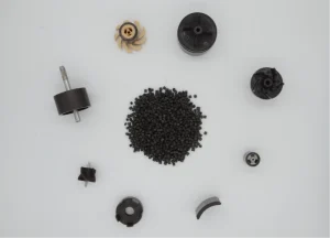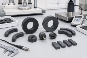


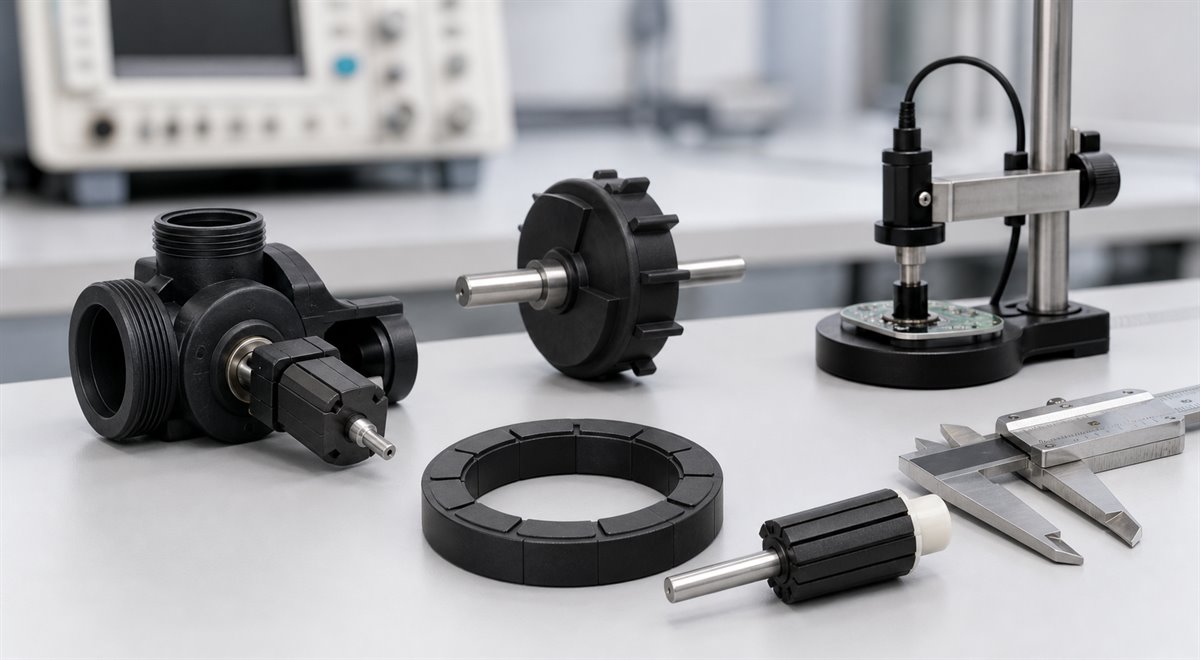
Industrial automation does not usually fail because a magnet is missing from a drawing. It fails when the magnet, shaft, housing, sensor, air gap, and production process are treated as separate decisions. A flowmeter rotor may need a tiny molded magnetic blade that spins freely in water. A robot joint may need a multi-pole encoder ring with repeatable angular output. A micro motor may need a rotor that survives speed, heat, vibration, and balancing requirements.
In each case, the practical unit is not only a magnet. It is a magnetic assembly: a designed combination of magnetic material, molded geometry, insert features, magnetization pattern, and inspection method. For OEM engineers, that shift matters because the right assembly can reduce part count, stabilize sensing performance, and make volume production easier to control.
This guide looks at magnetic assemblies for industrial automation through common examples: flow rotors, pump rotors, magnetic encoder rings, motor rotors, and sensor targets. It also outlines the design and validation questions that should be answered before sampling.
What Makes a Magnet an Assembly?
A standalone magnet is specified mainly by material, grade, shape, tolerance, coating, and magnetization direction. A magnetic assembly adds mechanical and functional relationships around that magnet. The drawing may include a shaft, bracket, sleeve, impeller, plastic carrier, bearing surface, mounting feature, or sensor datum. The inspection plan may include not only dimensions, but also flux at a defined air gap, waveform, pole pitch, runout, insert retention, or dynamic balance.
In industrial automation, this assembly-level thinking is often more important than maximum magnetic strength. A magnet with higher Br is not automatically better if it creates unstable sensing, poor concentricity, difficult assembly, or cracked parts under operating stress. A moderately strong bonded magnet may perform better when it is molded into the correct geometry and validated under the real working condition.
That is why many automation programs evaluate injection molded magnets, bonded magnetic compounds, and insert-molded structures early in the design phase. The goal is to control the magnetic field and the mechanical interface at the same time.
Flowmeter Induction Rotors: Small Parts, Tight Functional Windows
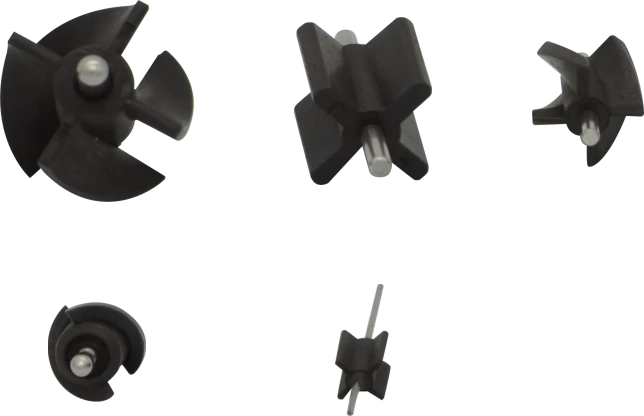
Flowmeter induction rotors are a good example of why magnetic assemblies need to be designed as systems. The part may look simple, but it has several jobs. It must rotate smoothly in a fluid path, generate a stable induction signal, resist breakage at thin blade sections, and hold its shaft or insert accurately enough for repeatable assembly.
Chase Technology’s industrial automation application data describes flowmeter induction rotors made from ferrite and PA12 or related material systems. These rotors can be injection molded into a cross shape, with a metal axis used as an insert to reduce downstream assembly cost. Each blade can serve as an N or S pole, allowing the rotating blade to generate the signal used for flow data. Rotor sizes can become very small, so material toughness and flowability are important when thin sections must fill reliably without cracking.
For engineers, the design question is not only whether the magnetic material has enough output. The rotor must also meet requirements for blade symmetry, shaft alignment, friction, fluid exposure, and signal stability. A small geometry error can create mechanical drag or magnetic signal variation. A material with poor flow can create weak thin spots. A shaft insert with poor retention can become a field failure.
Pump Rotors: Magnetic Function Meets Fluid and Balance Requirements
Pump rotors sit at the intersection of magnetic performance, fluid resistance, and rotating mechanical design. In water pumps, oil pumps, and compact fluid-control systems, the magnetic component may need to work with an impeller, bearing, sleeve, shaft, and housing. The rotor cannot be evaluated only by a surface field number because the finished pump cares about torque transfer, balance, temperature, chemical exposure, and lifetime stability.
Bonded magnetic compounds such as ferrite/PPS or NdFeB/PPS can be used when temperature resistance, moldability, and dimensional control matter. In some designs, the blade and rotor are molded as one integrated part. In other designs, the magnetic rotor is molded first, then the blade or carrier is formed by a secondary injection process. Both approaches can reduce tolerance stack-up if the tooling and process are planned correctly.
For automation equipment, pump rotor validation should include magnetic output, rotor dimensions, runout, shaft retention, dynamic balance, thermal cycling, fluid exposure, and start-stop durability. If the application is sensitive to noise or vibration, balance and concentricity may become just as important as the magnetic material selection.
Encoder Rings for Position and Speed Feedback
Magnetic encoder rings are widely used where rotary position or speed information is needed in compact mechanical systems. Robotics, stepping motors, automated handling equipment, compact actuators, and feedback modules all depend on stable magnetic signals. The ring may be a single-track or dual-track design. Pole count, pole pitch, ring concentricity, radial thickness, and sensor air gap all affect the final output.
For a deeper selection guide, see the related article on magnetic encoder magnets for rotary position sensing. The key idea is the same: an encoder ring is not only a ring magnet. It is part of a signal chain that includes the magnetization fixture, mechanical datum, sensor IC, air gap, electronics, and software interpretation.
In robotic joints and stepping motor feedback systems, the benefit of an integrated molded ring is that the magnetic track can be positioned relative to the bracket or shaft during production. Direct molding onto a bracket or carrier can simplify assembly and improve dimensional repeatability. This is especially valuable when pole spacing is fine and the signal must remain stable over temperature and vibration.
Motor Rotors and High-Speed Automation Components
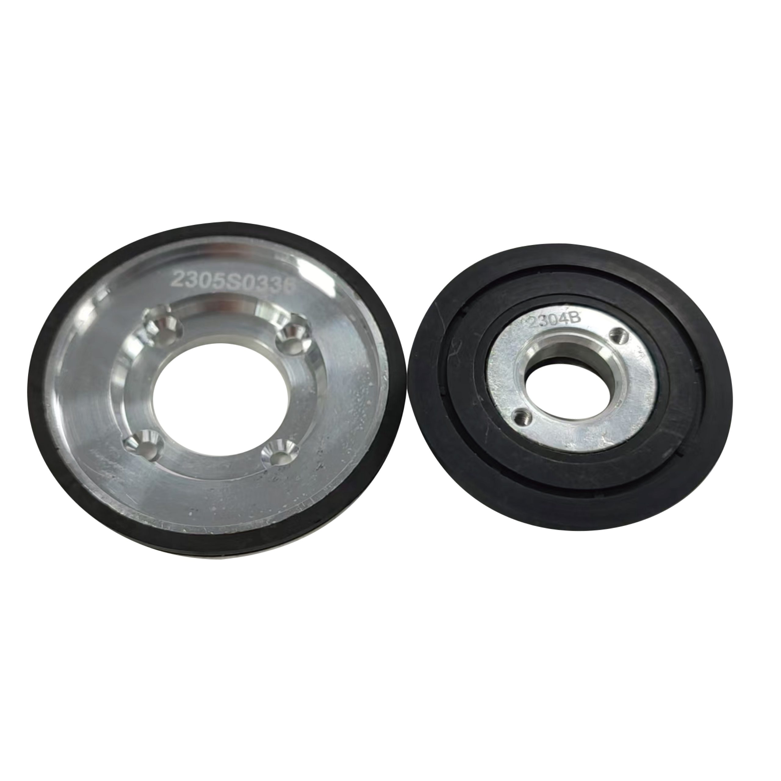
Motor rotors are another area where the finished assembly matters more than the magnet alone. A rotor magnet may need to fit a shaft, hub, sleeve, fan, bearing, or balancing feature. In small BLDC motors, high-speed motors, actuator modules, and automation drives, the rotor must deliver magnetic performance while maintaining mechanical integrity at speed.
Sintered magnets can provide high magnetic output, but they are brittle and may require separate bonding or retaining structures. Bonded and injection molded magnet solutions can offer geometry freedom, integrated features, and improved process repeatability. The right choice depends on flux requirement, speed, temperature, rotor diameter, allowable inertia, assembly method, and cost target.
High-speed components need special care. At elevated rotational speed, the design should evaluate centrifugal stress, insert strength, thermal expansion, balancing, and any risk of crack formation. A molded magnetic assembly can be attractive when the rotor needs ribs, sleeves, shaft features, or integrated geometry that would be costly to add after a sintered magnet is produced.
Choosing Material and Process for Industrial Magnetic Assemblies
The best material depends on what the assembly must survive and what signal or torque it must produce. Ferrite bonded compounds are often selected for cost-effective, corrosion-resistant parts. Bonded NdFeB compounds can increase magnetic output in limited space. PPS, PA12, PA6, and other resin systems are selected according to temperature, fluid contact, strength, dimensional stability, and molding behavior.
Process choice matters just as much as material choice:
| Assembly Need | Common Process Direction | Why It Matters |
|---|---|---|
| Complex rotor or sensor geometry | Injection molded bonded magnet | Forms thin features, holes, hubs, blades, and datums in one molded part |
| Metal shaft or bracket integration | Insert molding or overmolding | Reduces secondary assembly and improves positional consistency |
| Compact ring with higher magnetic loading | Compression molded bonded magnet or sintered magnet | Can be suitable when geometry is simpler and output density is the priority |
| Fine multi-pole encoder signal | Molded ring plus controlled magnetization fixture | Controls pole pattern, concentricity, and sensor-facing waveform |
| Fluid or thermal exposure | Resin and powder system matched to environment | Improves stability under water, oil, heat, humidity, or thermal shock |
For a new project, it is usually risky to choose material first and ask the toolmaker to solve the rest later. Magnetic simulation, mold flow, insert retention, magnetization, and inspection should be considered together. Chase’s simulation, tool making, and quality control resources are relevant because automation assemblies often need magnetic prediction, production tooling, and verification to match.
Conclusion
Magnetic assemblies for industrial automation should be designed around the function they perform: flow sensing, pump rotation, motor torque, encoder feedback, or position detection. Flow rotors need small molded geometry and fluid-friendly reliability. Pump rotors need magnetic output plus balance and environmental durability. Encoder rings need accurate pole patterns and stable sensor-facing waveforms. Motor rotors need both magnetic performance and mechanical robustness.
When these parts are treated as assemblies rather than isolated magnets, engineers can make better decisions about material, molding process, insert design, magnetization, and validation. The result is not only a part with magnetic strength, but a component that can be produced, inspected, and trusted in the equipment it supports.
FAQ
What is a magnetic assembly in industrial automation?
A magnetic assembly is a functional part that combines a magnet with mechanical, sensing, or rotating features. In industrial automation it may include an insert-molded shaft, bracket, rotor body, encoder ring, sensor target, or plastic carrier that controls how the magnetic field is used in the equipment.
Why are injection molded magnets often used for flow rotors and encoder rings?
Injection molding can form complex magnet geometry, thin features, inserts, hubs, shafts, and integrated carriers in one production step. This is valuable when the magnet must also control assembly cost, air gap, pole position, or rotor balance.
How should engineers validate encoder ring magnets?
Encoder ring magnets should be checked at the working air gap with the selected sensor IC or a representative magnetic probe. Engineers should validate pole count, pole pitch, waveform amplitude, phase error, concentricity, runout, mounting datum, and temperature behavior.
Can one supplier handle both the magnet and the assembly design?
For many automation projects, it is helpful to work with a supplier that can review magnetic material, tooling, insert molding, magnetization, dimensional inspection, and magnetic validation together. This reduces the risk of optimizing the magnet while missing assembly-level performance.